SMS CONTROLLER  GXL88 (extended) User manual    French     Dutch
This is the full manual of the GXL88 controller which includes the descriptions of practically all the possibilities. Do not be worried by this large amount of information because your application will probably ask the attentive reading of only a few chapters of the list of basic functions below. Doc date: mart 2018

All [PW commands] are sent as SMS to the controller. A command error will return a contextual info SMS showing the details of the command. "Pw" is the controller's default Password or Code that is 0000 until changed and is also the only case-sensitive command. Not to confuse with the SIM pin code that should have been previously removed before insertion at the SIM holder S1.

Send SMS command [0000 ?] to the controller from your mobile phone and you will receive an SMS listing the basic (most used) functions. Send [0000 ??] for a list of the extended supported functions. Do not include the [ ] command delimiters from the below examples. So any first letter command send to the controller will make it send back a short memo of the corresponding function right on your mobile phone. Example: [0000 R?] will reply with infos on how to control the output Relais.

The controller can operate in one, two or three different or simultaneous modes:

1- SMS / GSM / GPRS SIM must be there inserted and supplied antenna connected (see G?).

2- Internet. The internet module must then be inserted and an UTP cable connected to the router. This way of working gives the advantage of having all the parameters at a glance (see i?) .
  Commands via SMS / Internet or PC have exactly the same syntax and so are written in the same way .

3- Via a PC connected with the serial cable and with the PC program installed . This mode is usually chosen when no internet and no SIM are needed to monitor the controller inputs/outputs locally as extension to the PC. The GXL88 is a high performance configurable controller and so can also be used to solve many automation issues (see PC).

If the SIM has a pin code, delete it primarily using a mobile phone and check that you can send/receive SMS with the SIM without any PIN code. A prepaid SIM is good enough to work with. Insert the SIM card at the S1 SIM holder without touching the SIM connections or holder by hand and when possible with a non-powered controller (SIM and holder can be cleaned with alcohol). After that, connect the antenna and plug the adapter into the wall power outlet. You are then ready to check and get familiar with its functionalities before definitive installation.

If the optional internet module is plugged in inside the controller and configured, it would be more advantageous and faster to use the internet to continue to study the functions of GXL88. The browser of your choice can be used since no special program is needed to access the controller via the Internet. You only need to know the IP address, Port and controller page name. A fixed IP address is recommended and your router must be configured (see i?).

ANY change on Inputs, Voltages, Temperatures, Level, Time, etc, can force to switch ANY chosen output(s) and send Warnings and Alerts messages to a specific number at chosen (threshold/edges/compare) values.
Any of those events can also automatically or after a wanted delay, force/execute a local command just like an SMS command sent to the controller could do and send message to one or more of the 35 numbers in list.

The controller can send different kinds of messages.
Info and function configurations: There where the different settings are programmed.
Junction Warnings: Optional less critical messages when at low/high edges
Alerts: Critical messages for volts, temperature, level, etc < and > edges.
Alarm: Alarm message that works on alarm inputs Ai1 to Ai8 changing states.
         
Basic Functions listing.
    Shows basic list in return SMS             [Pw ?]
    The Alarm. Ai, AL, AnF Inputs delays       [Pw A?]
Changes/edits Input and Output names       [Pw E?]
          Factory parameters restore                 [Pw F?]
          GSM network connection parameters          [Pw G?]
    HH:MM:SS for time related functions        [Pw H?]
    Internet config, IP address etc...         [Pw i?]
    Numbers where to send to. NL nrs listing   [Pw N?]
Password  (default 0000)                   [Pw P?]
Outputs R1, R2, R3, R4 and R5 to R8        [Pw R?]
S+ Reply with Status-SMS.                  [Pw S]
        
Advanced Functions listing.
?? Extended functions messages types          [Pw ??]
AC Grid voltage, Voltage supplyRST L1,2,3   [Pw AC]
Junctions Inputs to Outputs. JS JM JnnFx   [Pw J?]
Interval timing on Output n                [Pw K?]
Monitor, audio Mic. Status on call M9      [Pw M?]
SS   Extended status from V1 without Outputs  [Pw SS]
T1 T2 Temperature. Alert and Control          [Pw T?]
V1 V2 V3 VS Voltage alert and control         [Pw V?]
Z1 Z2 Z3 Multipurpose sensors inputs          [Pw Z?]

Messages Types ,  Basic schema , PC program , Power Meter


Some to all the functions described may be configured and used simultaneously as needed. The ones that are not configured, will simply be ignored by the system. We start with the basic functions that cover the greater part of the needs and especially S, N, R and A.

You can start sending commands to the controller after the LED in the middle (41) flashes green (or red if the alarm is ON) at a rate of 1 second ON and 1 second OFF. If the LED only gives brief flash each second instead of 1s /1s on/off, then the SIM card is not registered to the cellular network operator. So no GSM and/or SMS traffic can be performed. Then better check the SIM card and  G? for details.

The yellow LED on the left (28 ) will indicate if the delivered line adapter 240VAC to 12Vdc feeds the controller with 12Vdc at (29)+ and (30)-.
The red LED at terminal (54) most right shows with 1 flash each 2 seconds if the connection to the GSM network radio module is correct or also 1 brief flash each second when not registered to the cellular network

References to the terminal / controller connection are indicated in this manual in brackets () and match the numbers written on the box. Thus and as an example, the two connections of the relay R1 are (1) and  (2 ) and the three pins of T1 temperature sensor plug are (38) (39) (40). Always check carefully when connecting anything.

The following examples below show commands sent to the controller from the mobile phone as
BOLD BOLD BOLD between [ ], and messages sent from the controller to the cell phone in GREEN. Do not send the [ and ] with the commands.


The chapters are in order of functionality. Please use list or ___ for quick access.


S    General status informations.  SS   S+.          

          [Pw s] to the controller will make it reply with the basic status.

R1 ON Jn Jn      On/Off, active junction for this output
R2 ON xxx        xxx = remaining time On if timed
R3 Off VS        Relais 3 Off. Jn VS could switch R3
R5 ON Jn         See or send [Pw R?] for relais infos
V1 13.5          BATT Voltage at (31) Batt Supply input
V2 53.9          External Voltmeter V2 at (33)±80Vdc
T1 18.2          Thermometer T1 (0-95). Terminals (39)
T2 -24.2         Temperature T2 optional (-40-125) (47)
AC=1 000         1 or 0 Grid at ADAPTOR. L1,2,3 control
GL 24.1%         Tank level or else. Z1 was renamed to GL
Ai: 01101100            Inputs Level Ai1 to Ai8.  
A=ON M9          Alarm On/Off, Mic On/Off, Status on call
13:45 Hxx        controller Time. Hxx status source if H?
Amsterdam-NL     The name/location of the controller

Status message items can be removed or added. So command [Pw V1-] will remove line V1 from the status s and [Pw V1+] will make line V1 visible again. Same for V1, V2, V3, Vs, T1, T2, Cj, Cp, Pt, Pd, Ai, Z1, Z2, Z3,

[Pw ss] will send back the current status from line V1.

V1 12.1         Voltage (31) BATT (0-16Vdc MAX) 
V2 53.9         Voltage (33) V2 ± 0-80Vdc
V3 0            Voltage (37) V3/L3 (0-16Vdc MAX)
VS 12.2         Voltage Supply ADAPTOR (29)+ (VS 0-16Vdc)
T1 22.2        
Thermometer T1 (0-95). Terminals (39) 
T2 -24.2       
Temperature T2 optional (-40-125) (47)
AC=1 0ST        Only L2 and L3 ON. L1 is Off
GL 24.1%        Multi purpose inputs Z1, Z2, Z3
Z2 10.3         for Level, Température, Volt etc
Z3 25.2'        Z1,2,3 can be renamed to GL T3 V5, etc
Cd 11:23        Run time counter. DAY
form 00:00
CT 1982:13      Run time counter TOTAL
Pd 240          Pulses counter. DAY
form 00:00
PT 2354148      Pulses counter TOTAL
i0-7: 10111111 
Inputs Level Ai1 to Ai8
A=ON M9         Alarm On/Off, Mic On/Off, Status on call
13:45 Hxx       Controller Time. Hxx status source if H?
Amsterdam-NL    The name/location of the controller

Status replies are sent back to the number that has made the request [Pw s] [Pw ss] or to number N1 in list when the calling number is not recognized. So N1 is needed here (see N?).
[Pw s+80] is also valid and will send the status to N1 only after 1 minute and 20s. Delay from 0 to 65Ks are possible so [Pw s+3600] will give a status s after one hour (ss when value is odd).
See H? for infos on configuring the system for daily or repetitive status messages. 


A    Alarm Inputs.    AL list Alarm Delays.   AnF Force Alarm.
         

Up to 8 alarm inputs can be directly connected. The sensor (or group of sensors) can be any (magnet, pressure, temp, …) switch contacts directly connected to the controller inputs. Any device, like motion detectors or fire alarm sensors with a potential free output, that can make or break a circuit (between GND and the input), like a switch will do, can be used.
Be sure that no voltage (or in any case no more as +12Vdc) will be applied on the Ai1 to Ai8 inputs. In fact, circuit shorted to GND or open is enough to make the input trigger an alarm (or a Junction event, see J?) and is a good way to drive the inputs Ai1 to Ai8.

When the Alarm is On or in O+ mode, any level change on inputs Ai1 to Ai8 will trigger an alarm event and make then send alarm SMS after the corresponding Input Delay AL. Starting from N1 in the number list and ongoing, either until parameter aD or the first empty position found in list or that any command, is received.
The controller can also make call a fixed or mobile
number to let hear what the alarm is about via the internal mic (position (52) of the box). As explained at N? the number should then be preceded by =! to make it call and not send a message.

Several SMS can be sent according to the parameter aD which is at
5 by defaulf. This parameter is visible by command AL below. To put it to 3 for example, send: [Pw aD 3] to the controller. Parameter aR makes it possible to switch On/Off an output when the function Alarm goes On/Off and aS a lamp or siren or else in case of alarm event.

A manual switch connected to one of the inputs Ai1 to Ai8 can turn the Alarm to On when shorted to GND and to Off when released.
Parameter aB will tell on which input the switch is connected. So [Code aB 6 A6 180 AL] configures Ai6 as the manual Button input and will give him a delay of 3mn and AL makes send back the Alarm input listing and settings where the result of above command can be checked.

Command  [Pw A On] or [Pw A Off] to the controller can be mixed with the manual switch but command [Pw A O+] will prevent the Alarm to be set off with the manual switch.

A received ALARM SMS message look like:

!ALARM! A2       Alarm show !ALARM! first! and position
BACKDOOR         The name given to the input
Trig.level=0     Low level GND Or High(1) or floating
Delay: 4s        Corresponding input delay. See AL below
Ai: 10010011     Alarm Inputs Level Ai1 to Ai8
Pw S, AL, J?, M? Suggested commands
aR 0 0           Relais switched by command A On or Off
aS 0 0           Siren triggered on alarm event. see AL
aB 6             Local Button/switch for manual command
SMS 3/5 (2)      Message 3 of 5, see AL/AD. (2)*
13:02            Controller Time at alarm event
Paris-02         Controller Name/location. [Code Dai Paris-02]
                
* How many alarm trigger since last Alarm On

    AL    Alarm List Delays.           

Each alarm input Ai1 to Ai8 can have a delay assigned to it. This is the delay before an alarm SMS will be sent after the corresponding input level change. So [Pw A1 3 A2 125] will assign input 1 delay to 3 and A2 to 125 seconds. Any delay at 0 (zero) except for the button, will suppress the Alarm function on corresponding input. Delays can be from 0 up to several minutes.


When the Alarm function is turned On with a Button connected to an input, the corresponding delay will then be the exit time before an alarm will be triggered. When On via SMS the Alarm is immediately turned On and there will be no time to exit the place. If a switch is used, setting the button delay to very low value 5 is okay. Use it and see the color of the internal middle LED (Red is Alarm On and green will be Alarm Off).

Command [0000 AL] will make SMS you the input delays list+names.

1=3 A1       Ai1 delay is 3s. From 0 à 65Ks (Kiloseconds)
2=4 GARAGE   A2 delay = 4s. [Pw A2 4 ea2 GARAGE]
3=j=60 A3    1mn for A3. AND one junction is setup for A3
4=1 Front Window Delay to 1 make only send 1 sms to N4
5=125 A5     A5 delay = 125s [Pw A5 125]
6=b=180 A6   On/Off button for the alarm, delay 3mn
7=J=0 IN-7   No alarm on Ai7 but junction [Pw A7 0 ea7 IN-7]
8=1200 Cellar Delay 20mn! [0000 a8 1200 ea8 Cellar A off s]
aR 4 1       R4 to ON together with the Alarm turn ON
aS 3 30      R2 (siren/Lamps) 30s On on alarm event
aD 5         Send up to 5 alarm SMS, N1 to N5
Pw A? Ai?    Suggested command for infos on Alarm
A=ON M0      Alarm is ON. No auto answer on call

Possibly, A1 to A8 can make send only one single SMS, respectively from N1 to N8 on alarm event. This if corresponding A1 to A8 delay is set to value 1 as A4 above. If Alarm is ON, only one SMS will be sent to the number programmed at N4 on alarm trigger event at input Ai4.

[Code aR 4 1] will automatically set output R4 ON when the Alarm function is turned ON and [Code aR 4 660] would set R4 on for only 11 minutes(=660s). Turning the Alarm to Off will switch R4 off anyway. This can be handy for a lamp, camera or any device that should work along with the Alarm. So here, 1 is to switch ON and sss is for timing up to 65Ks. 

[Code aS 3 45] will make output R3 switch ON for 45s when an alarm event occurs. A siren or a lamp or any device can be connected to the chosen output 1 to 8 (R3 here). aS needs a timing and does  not switch if value is 1 or 0. The aS output goes on instantly when the alarm is triggered (at input delay start) if aS timing has an even value. If the aS timing value is odd, the siren (or else)  will be put on only after the delay
of the input that caused the alarm.

Inputs Ai1 to Ai8 can be named so that a message becomes more intuitive. Command [0000 eA4 Front_Window] for example renames A4 in "Front Window"Input names can have up to 15 characters. Underscore "_" will be used to include a space character (see e?).

If the alarm delay is > 0 and a junction is also configured for the input, both alarm message and warning can be sent for the same event trigger on a level change . When an Input is only wanted as a Junction input, what is generally the case, and not for an alarm input, just set the corresponding delay to 0 [Pw A7 0].
For example: [0000 A5 0 Ji5 0 0 0 15 N15 YourNumber] would clear A5 delay and setup a junction for input Ai5. This junction will only send a warning when Ai5 changes level to YourNumber being at N15. The junction will be used when a warning is always wanted on an input change. Please see at J? to know more about the Junctions function and remember that there is no alarm when delay = 0 and that a junction can work no matter the alarm mode.

Alarm event can also locally execute a commands when the commands replace a number, written at any number list position. So for the above example, if position 15 had "=s" written at position N15, a status could be sent on Ai5 input change.

    AnF    Force and simulate alarm event for test.          

When the Alarm is on watch, A=On or A=O+, command [Pw AnF] to the controller will simulate an alarm input n change and trigger an alarm. Replace n with 1 to 8. So to test on A2 for example, send [0000 A2F]. 
When the above command can remotely do it from SMS or even from the internet, locally changing the input level by shorting it to GND and releasing it (open circuit) or the opposite, will of course trigger an alarm as well if the Alarm function is in the On mode.


Ai(1 to 8) will normally be shorted to GND or left floating but can also be driven by a voltage from 0V(GND)=(Low/0) to 15V(High/1). However, floating inputs Ai1 to Ai8 are at ±3.1 Volt level and input level change occur at about <2V for Low/0 and >2.5V for High/1.
L0, L1, L2, L3 and T1, Z1, Z2, Z3 can also be used as alarm inputs, because they have programmable trip/trigger level with the functions < > or junctions, but only send alert and warning messages not Alarm...


N     Programming the numbers where to send Warnings, Alerts and Alarms.
         

Command [Pw N?] will reply with an SMS that will remind you what you can do to program the numbers.  At least one (mobile) number needs to be programmed at position N1 because in many cases, number N1 will be the one where the controller will send an SMS. To add a number to the list at position Nn, just send [Pw Nx Nunber]  where Nx can be 35 maxi.

[0000 n3 065154422 n2 0201223314 N10 +322563551521 nl] could program many at once and as a control, send back the list if the command is terminated with
nl.

The Number list (phone book) will contain a short string of text(memo), or the phone numbers pointed by field F4 where to send the junction warnings (see below J?), direct local commands to be executed when vectored to. It can also contain additional so-called "AT commandos" executed at GSM radio module initialization for other GSM radio configuration.

     NL   Listing the numbers.

[Pw NL] sends back an SMS listing from the first begin:

1 0654420720     Number N1. This number is necessary
2 0206222240     N2. also for Alarms, Alerts and Warnings...
3 +133453256331  Foreign numbers, last Alarm number! no N4
10 =!10101010    No SMS but voice call. Also Alerts/warnings**
12 <0658520220   Alert and/or Warning only for Low/0/Off
15 =R2 120       Switch R2 On for 2mn if vectored to N15
18 Anytext15Chrs Store short text up to 15 characters
19 02055254450   To fixed land line. SMS read out loud by operator
20 =s            Status to N1 when vector N point to N20    
24 =R4 180 s+31  R4 on for 180s, Status ss to N1 after 31 sec

[PassWord NL 25] sends back a list from indicated position.

25 >0696465498   Alert or warning only for High/1/On
26 Any54625444  
Another short text up to 15 characters
27 =R2 0 R3 25 t If vectored to N27. Test it with [0000 !N27]
28 AT+CMD        Executed at GXL88 initialization (N20-N29)
33 if Number     GPRS connection errors report
34 if Number     Eventual program errors report
35 =ss           Force send status from V1 to N1 immediately

Numbers are listed in order from 1 to nn until SMS is full. [Pw NL 20] will make send back an SMS listing with numbers found from position 20 until no more are found or SMS full again. A normal SMS can carry up to 160 characters maxi.

Field {JN} of a junction command pointing to a Nn in  the
list numbers can make send a Warning for < Low/0/Off event (like N12 above), the opposite > High/1/On (like N25 above) or both events. See at J? for more infos on this matter. The command will be executed first and when wanted, a message will  also be sent after that. This as at N24 and N17 at the above example where status and T config is sendtback.

A command can also replace a number and be executed when vectored to. Like at N10, 15 , 20, 24, 27 and N35 in the example above where "=" is needed at first position to specify a command line and not a number. The command line can here also have 15 characters,
same as for the phone numbers or memos.

For example, command [Pw JL2 0 1 4 24 N24 =r4 on s+31] to the controller will virtually connect  input L2 to output R4 with the Junction JL2 and write the local commands to be executed when the junction will trigger.
After that, power On (high level) on L2 will switch R4 Off and make send a status ss to N1 after 31 seconds. Power Off on L2 (low level) will make switch R4 On again and also send to N1 after 22 seconds. Note here that the "=" command will be written as last, because adding a command to the list makes send back a number listing for check...

** Junction field {JN} or second alert number pointing to N10 could make the controller call the number instead of send an SMS.
So if in the above list N3 is configured with a ! call command with
[0000 N3 =!066742125], the number will be dialed. The called side is then able to immediately listen to the controller's call upon accepting the call fixed or mobile.
When this command is used with the alarm function, program the last number as a caller with =!number like above with N3 or the last number indicated by parameter aD. So if 5 alarm numbers are programmed, make N5 the one that will be called for the mic function.

The number list can also contain special AT commands (from N20 to N29) that will be executed at GSM radio module setup. So, also at system power-up and after command  [Pw Fz] or in any other cases, making the built-in radio module initialize/restart. Great care must be taken using AT commands to the GSM radio, because doing so without knowledge of the matter will probably at least interrupt any communication!

Simply begin writing Alarm numbers into the list from N1, one or more, one after another. Parameter aD is at 5 by default and so allows to SMS a series of up to 5 alarm numbers or to the first empty position. So 2 or 3 numbers will be okay too.
Then program the optional Alert numbers for the < and > functions for Ln, Vn, Tn and Zn. This < > function normally sends to N1, but each of them have a second (rarely used) programmable alert number, so that an alert can optionally be sent to two numbers.
Finally program the warnings numbers used by the Junctions. Also optional because junctions can also work without sending warning message. If used, they can be best programmed after or together with the junction setup (see J?). 


R    Outputs Relais R1 to R4 and output R5 to R8.
          

The four power outputs let you remotely drive any machine or high power equipment with a simple SMS command*. Wiring the outputs require
your full attention and must be executed with care. Let an electrician do the job! Always disconnect the power, low ánd high tension, when manipulating the output wires!

Output R1, R2 and R3 are (No/NC) and Output R4 is (NC/NO/NC). The output can sustain up to 10A and from 12V to 260VAC(2500W) can be switched. [0000 R?] gives back a help-SMS on the Outputs possibilities.
 
Timing up to 65500 seconds (about 18 Hours) can be added to the command. No timing (just: On) will make the output simply switch On until an Off-command arrives.
To switch an Output On send command [Pw R1 on] and to switch it off send [Pw R2 off] or
[Pw R2 0]. Multiple commands are supported in the same SMS command to the controller; [Pw R3 on R2 0 R1 on 555 R4 1220 s]. The here optional trailing s makes the controller to reply with a status SMS that will show the new outputs status including timings left before Off.

Outputs can be given a meaningful name such as Pump, Light, Motor and you can rename the Output as you like.
So if Relais R1 is renamed to Pump, command [Pw Pump 600] will switch the pump on for 10min and [Pw Pump 0] stops the pump either way, also before the 10mns are done  (see e? for editing the In- and Outputs).

The output listing in a [Pw s] status SMS command:

R1 187 Jn      187s left before Off. See also at s?
R2 Off as I2   R2 can go to ON by alarm trigger (aS)*
R3 ON ar       Could also be On from [Pw A On] (aR)*
R4 ON V1       R4 could have been set On by Junction V1
R7 3600        Was [Pw R7 4000], see just below A5 to A8

*As seen before at the Alarm function, aR and aS make switch the output When Alarm to ON and on alarm trigger (see AL).

R5 to R8 outputs are shared with the inputs Ai5 to Ai8
To use any of them as an output simply program the corresponding input delay Ai5 to Ai8 to 0(zero). The input will then become an output at first output command and also become visible in the status s message. Junctions Ji5 to Ji8 remain functional and therefore, if setup, will also react on R5 to R8 output changes. Ex:
[ Pw a7 0 r7 60 s] or [ Code a7 0 r7 0] to keep Ai7=R7 down to GND.
R5 to R8 will become inputs again by writing corresponding Alarm delay n to any>0 value: [Pw An any>0]

A5 to A8 can also be used as Low power digital outputs having 0 volt level when Off and about  4.0V at 3mA when On. Just enough for a LED or the input of a power driver. See also at H? to switch any output at wanted time.

*DANGER: Great care is recommended when blindly switching any machine or device remotely. Furthermore, the switching order, that normally should arrive in a few seconds, could arrive delayed at the controller due to a GSM network overload or any other possible unexpected reasons. Really know what you do and always disconnect the controller outputs and power before doing any work or maintenance to prevent electrical shock and mechanical hazards in case an output becomes unintentionally driven.


E    EA     Editing Alarm Inputs A0-A8.
          

To name or rename Input A2 into Backdoor, send command [Pw EA2 Backdoor] to the controller.  An alarm SMS triggered by A2 will then show;

!ALARM! BACKDOOR     Alarm message show !ALARM! first!
A2=Low(0) TRIGGER!   Or High(1), + remaining of the message.

Actual names are also listed in the delay timing SMS by [Pw AL] Command [Pw A?] to the controller sends back the function infos.

Alarm input names can have a maximum or 15 alphanumeric characters maximum with no space* in the Input name. So [Pw ea2 Sensor-2!] will show "!ALARM!  SENSOR-2!" in an Alarm message.
*[Pw EA4 Front_WINDOW] will name A4 to Front WINDOW. Note that the underscore "_" will make display a space in the name.

The Input names Ai1 to Ai8, visible and listed by command [Pw AL], can all have up to 15 alphanumeric characters.
The same names will be shown in a Junction warning message for corresponding Ji1 to Ji8 input.
Choose a meaningful name for the Ain inputs and always use its source name, Ai(n) to remain it and not its edited name.


       ER    Editing Outputs Relais names.

To give R1 the name PUMP, send SMS command [Pw ER1 pump] to the controller. To Edit Output R2 to LIGHT, send command [Pw ER2 light] and for Rn [Pw ERn New_Name]. Output names can be edited with a maximum or 15 alphanumeric characters with also no space in the output name.
Input and Output names are things. Input names are listed with [Pw AL] and Output names with [Pw S]

Any of the Output R1 to R8 edited to only 1 character will not be listed in the status message, but will not lose any functionality. This can be handy to shorten the status message especially for unused outputs.
So [Pw er3 3] will shorten the status message with one line.
Its new name is now 3, so [Pw 3 3] could switch it for 3 seconds and [Pw 3 13] for 13 seconds. So rename unused outputs to only one character in order to reduce the status message when it becomes too long to fit the status SMS.
Keep single letter output names consistent and edit the outputs like, R4 to 4,  R5 to 5 to avoid later difficulties remembering what they where named.
Actual Output names are listed in the status SMS

so [Pw s] to the controller will show the output names.

PUMP OFF       R1 renamed by [Pw ER1 POMP]
Lamp ON 320    R2 by [0000 ER2 Lamp]
R4 OFF         no R3! renamed by [Pw ER3 3]
etc....        Default name is always used to rename an output

After editing, the Alias will be used to command any switching on the outputs. So choose short, meaningful and easy-to-remember output names. To switch On the PUMP for 15 minutes and the Lamp for 1H, send command [Pw pump 900 Lamp 3600] where lower/upper cases are of no importance.


    To name or to rename the controller.

Command Dai found at menu D for Data and GPRS gives the possibility to give a name to the controller. This will be very convenient when more than a single controller need to be monitored. The name will then appear at the end of the received message from the controllers,.

To name it Paris-02 use
[0000 Dai Paris-02] to remove the name [0000 Dai   ] (2 spaces after Dai)...


    EZn to change the two characters of Z1 Z2 Z3

This only can change to the two letters showing Z1, Z2 and Z3, but does not raise any influence on the functionality. These functions can be used for different sensors and therefore could better be listed by meaningful alias.
So a pressure sensor on Z1 could be aliased by P1, another on Z2 could be shown by GL and a Voltmeter on Z3 could be named V8.
 For example: [0000 ez3 V8 ez1 P1 ez2 GL] could do it all together...


    EPM  EP1 EP2 EP3  To name the PMC, phases or groups

The optional Power Meter Controller , its three phases or three groups of mono phases can also all be named. These names are only shown when accessing the controller via internet, but do not interfere with any functionality (see PM). 


    EFnn    To name the functions V1 to Z3

Functions V1, V2, V3, Vs, L0, L1, L2, L3, T1, T2, Z1, Z2, Z3 can also be named with up to 15 characters names. These names will be visible on the web page and on Alert- and Warning-SMS messages giving more meaning the the above abbreviations.

The controller's built-in server sends all the system infos on a single web page where different fields will show these edited names. The interface is obvious and a careful look will reveal almost all the function names and passing the PC mouse through a field adds more info at the tool tips.

To check the difference between internet and SMS mode, only write 0000 s at the navigator screen command line and push on the gray [Send] button. The normal status SMS will then also be visible at page refresh at the bottom. This works also for the other commands that will show the reply SMS at page bottom.Commands send via SMS, internet or PC will all have same syntax and do not need [ ] delimiters brackets included.
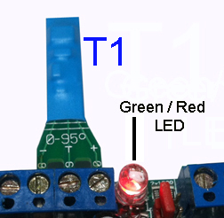
To name T1 in "Thermometer 1" send command [0000 EFT1 Thermometer_1]. For L1 [0000 EFL1 Phase_1]. Note here that because of the limited compatibility between languages, systems and navigators, punctuation marks should best be avoided.

For V1 send command [0000 EFV1 Battery_G1], V2 [0000 EFV2 Group_48V], V3, [0000 EFV3 Batt_G2] ,,,
For Z1 to Z3 [0000 EFz2 Oil_tank_G2]. Do not confuse Zn alias (at EZn above) with Zn function names.

The Fw1 to Fw4 have a particular functionality as explained in the "Functions expert" file...


Pw    Password  (default 0000).  [Pw P?]  for infos.           

The password shown as Pw in the example is 0000
(4xZERO) by default . To change it, send SMS [OldPassword P(NewPassword)].
The password is 3 to 7 characters
maxi, alphanumeric digits and/or letters and is case sensitive with no blank in it! Keep it short to make things fast and easy. So [0000 P(911)].

To change it to ABC, send SMS [0000 P(ABC)] and to change it again for "1+2=3" send [ABC P(1+2=3)]

If the password is lost or forgotten, disconnect all the controller power sources and any wire from Ai1 and Ai2. Short then Ai1 to Ai2 with a piece of wire and power-up the controller again and wait until the middle LED flashes at a 1 sec ON and 1 second OFF rate.
Default settings are then restored as in F? here just below, and the Password will be 0000 again.
See the new status information by sending [Pw s] and [Pw ss] and check all the settings again also restored to the default value! Ai1 is at box terminal (20) and Ai2 (21). Do not forget to disconnect Ai1 from Ai2 after that or the password will be reset to 0000 again after any initialization.


F   Factory parameters restore.
           

The controller can be restored to its default factory settings.
In case of a major problem, sending command [Pw FSRA] could solve the issue if the controller is still able to receive a command.
W
ait until the middle LED flashes at a 1 sec ON and 1 second OFF rate (if a SIM is installed) after a Force Settings Restore All command and use
then 0000 (4 x zero) as password that is also restored. Then start to re-program the parameters to the wanted values. Restoring the controller and the Parameters to the default factory settings can also be achieved with the password-lost-solution explained just above at P?.

[Pw Fz] only initializes the GXL88 and restarts the built-in radio and internet module, password and parameters remain the same. This action has the same effect (but from a distance) as removing and re-establishing the controller power.

[Pw Fg] Initialize the radio module
that connects to the GSM network. Only use it after changing some AT settings.

[Pw F?] shows relevant parameters.

FSRA (x) Delete/Reset All(Not N list)!
Pw Fz (z) restart system. (z) How many Fz so far
Use 0000 s after 30s.     (x) How many FSRA so far
See Pw G?/G+
GXL88 V2-15               Loaded firmware version 2 2015
Amsterdam                 Controller name / location

When needed, command [Code Fe] ((e)mergency) to the controler immediately stop any radio trafic (shut off the GSM module), see also G below. Commande [0000 sim 0 fe] will stop definitely because SIM 0 make the GXL88 works whitout any GSM trafic...


G    GSM network parameters         

The most right red LED at box position (54) shows that the SIM is registered to the GSM network when it is flashing with a brief flash at two second rate. If not lighting at all or each second briefly, the system can not receive nor send SMS message or call. Use then the internet if connected to or the serial link to PC if not. Always hold the SIM cart by the plastic edges and not the contacts.

    The reason could be one of these:
    SIM is not in the right socket, the system takes S1 by default also on two-SIM controllers (see command SIM 1 below)
    SIM does not make good contact in the socket! If clean, try to slide the SIM a half mm up and down in the closed socket
    SIM is dirty. Do not put fingers on the SIM or sockect contacts.
SIM and holder can be gently cleaned with 90° alcohol
    Use a normal cell phone to remove SIM code and test the SIM. The most simple SIM with no 3/4G will work

Command [Code G?] will show the following parameters:
   
Pw SIM 1            SIM mode 1(defaut) selected with [Pw SIM 1]
Mode=1 Used=1      
Selected mode and the one actually used
0,1,2,3(1+2)        Possible modes. 0, 1, 2 ou 3(two together)
Fg restart GSM radio! [0000 fg] reset and reconnect to network
Fe Emergency Stop! 
[0000 fe] Stop radio immediately!
Ant: 36%            Rx Antenna signal. < 12% become very low!
OP: KPN MOBILE      Name of actual connected cellular operator
IMEI: 563031015145201 
International Mobile Equipment Identity
V0: 4364            Voltage on GSM radio module (millivolt)
T0: 33              Internal contrôleur temperature, °Celcius 

When the list is incomplete use command [0000 G+] that will first make reload the parameters before sending the above message.

Mode SIM 0 will make the GXL88 controller to work without GSM connectivity. So SIM cards (also inserted) are ignored and all related GSM issues are discarded. This option will be useful when the controller is used to regulate some local systems that do not require external control or commands. When wanted, internet or PC serial connectivity is still available in mode SIM 0.
Regarding the possibilities, this controller is also a programmable control computer at very fair and competitive price!

Please note carefully that sending the command [Pw SIM 0] to the controller via SMS enables the SIM mode 0 and will consequently be the last SMS command received via SMS. So if the internet mode (if available) is not enabled before by 
[0000 i on]  the controller will only be locally accessible via the serial link to the PC.
[Pw SIM x fg] where x can be 1, 2 or 3, sent from internet PC via serial or internet will re-enable GSM communication when possible.

Mode SIM 1 is for SIM holder at S1 and Mode Sim 2 for S2. Select preferably SIM1 at S1 for controller having two SIM holders when only one SIM will be used as in most cases.
So command [0000 sim 1] enables SIM 1 usage and of course its SIM voice call number! SIM mode 2 will be configured when SIM holder S1 is bad or dirty. SIM 1 or 2  work both the same and SIM 3 makes use the first SIM available to connect to the GSM network.


H     H:M  setting for time related functions.
        

To set the controller software and hardware Real Time Clock (needed for all related Time functions) at 14:49, use [Pw H 14:49].  The clock can be adjusted before or after any other command. Like here with [Pw H 12:14 R1 Off s] 
The software clock also tells about unexpected system resets. Watchdog and control procedures will automatically reset and restart the GXL88 microcontroller on fatal software errors. By default and as control, a Status SMS is sent to number N1 3mn after power on or initialize when no command is received within those 3 minutes.
When the time shown in the status is at 00:03, a system restart is notified! After that, the software clock will synchronize with the hardware real time clock and automatically be set to the right time if parameter Hc is left at 0 and if no power interruption has occured.

SMS [Pw h?] to GXL88 lists all time related function settings.

Pw H 05:38       Actual controller time set by [Pw H HH:MM]
Hs1 3 12:15     
Status to N3 at 12H15 once a day
Hs2 1 00:10      Status to N1 at xx:10 each hour
Hsm 0 mn         Repetitive status time synchrone to Hs1 N
Hss 0 sec        Repetitive status SE at sec to HS2 N1 number
He1 6 00:00      Energy SE to N6. Répetitive (00:MM) or at HH:MM
HeM 22 mn        Energy status SE to N6. Répetitive on 22mn
HeS 800 sec      Energy status SE to N6. Répetitive on 800sec
HL 00:00        
Status to serial at HH:MM

HrA 4 08:30 20:13 R4 ON at 8H30 off at 20:13
HrB 5 22:45 07:03 R5 ON at 22:45, stop at 07H03
Hc 0 Hg 15       Clock ±s in Mode SIM 0. GSM test time

Status message sent from the function H will show its source as hs1, hsm, etc, at Hxx after the controller time line (see at s?).

[Pw Hs1 Nn 12:15] Will force a Status SMS to Nn (that can be 1 to 35), each day, at 12:15. [Pw Hs2 30 01:30] will send a second status message to N30 at given time, so here each night after midnight at 1 hour and 30 minuts. Both cases need a valid number at position pointed numbers list position.This will give a good daily control of the system.
[Code HS1 2 00:15] make the status to number N2 each hour at minutes =15. This simply because the HH field is left equal to zero! Hs2 can do the same and both functions can be used simultaneously to get two status messages per hour.
So command [Code HS1 1 00:15 hs2 1 00:45] could make send two status messages each hour to N1.

Status SMS are sent synchronized to the minutes of the time with Hsm function. Hsm uses the Number programmed at Hs1.
    [Pw Hsm 11] sends a status SMS at xx:11 , xx:22, xx:33, xx:44 and xx:55 at number written at Hs1.
    [Pw Hsm 25] sends a status SMS at xx:25 and xx:50 also at number programmed at HS1. (Hsm >2 <59mn)

Hss force sends status at Hss programmed interval value to the number pointed by HS2 N in the number list.
So command [Pw Hs2 25 00:00 Hss 600] will send the status at number found at position 25 in number list. This on the 10 mn here, but programmable from 1 to 65000sec. Writing 0 at "25" or "600" stops the function Hss and Hs2 will be ignored because 00:00 is invalid.
An interesting option for Hss will also be the possibility to send the status "ss" from V1. Status [s] form R1 is sent if value sec of hss is even and status [ss] from V1 if odd.
Please see [s] and [ss] again above about the status messages.

[Password HE1 6 15:31] force reads the Power Meter and then sends an Energy Status SMS [SE] to Number 6 in list. In this example every day at 15:31. If field HH of HsE is zero, only the minutes are worked out and the [Se] status will be sent out once each hour at MM = Minute of the controller enabled time clock.
So
[Pw HSE 8 00:35] makes send each hour at midnight and 35 minutes to number written in the phone book(number list) at position 8. (See at bottom the functions expert for the commands [Se], [Sx ]and [Si] to the controller making it read/setting the Power Meter.

Hem has the same synchron functionality as Hsm above. However the differences are that the message will be an Energie status [SE] and that it will be sent to the numbers indicated by HE1. See at Hsm for He1 same timing). Parameters Hsm and Hem can be programmed with a value >2mn and < to 59mn.

Command
[Hra 2 14:15 14:30] will make switch R2  output at 14:15 On, and then switches Off at 14:30 everyday. Function HRB has the same functionality and here also could be used simultaneously on the same relais output to get more switching times.
So [Code HrA 1 00:15 08:45 HrB 1 14:00 17:15 h] could make switch same relais N1 at different times.
See also the function "Klignoteur" that can switch very short time on big delays.

Hc is a clock correction parameter that can be used to tune the software clock only. If one thinks that the clock is too fast with 2s every days, the command [Pw Hc -2] can be used. For 4s a day too slow, use command [Pw Hc 4].
Parameter Hc can better be left to 0 (zero) when the SIM mode parameter is not zero, so that the software clock will automatically synchronize with the Real Time Clock that does not require any correction.
The hardware RTC is ignored while in SIM mode 0 and only the software clock will then be used, no matter the Hc parameter value. The default setting of Hc is 0 and SIM is 1. (see G? for the different SIM modes).
Whatever the H parameters settings are, the Clock(s) can always be set to the wanted time when adding
[ H HH:MM ] before or after an other command sent to the controller. Care should be taken so that here too, the command that makes return an answer is the last in the command line. So for example here; [Password N4 020452444 R1 Off H 17:51 ss].

The hardware RTC will normally take its power from inputs: BATT V1(31), ADAPTOR VS(29) and L3/V3 at position (37) of the box. As for some customer's needs, a CR2032 3V lithium battery can be inserted in the internal and optional receptor in order to move the controller without losing the HH:MM time.

Hg tells at which rate the GSM network connection control is done. Here at 11 and synchronous to the minute. Hg can best be left to this default value, but users can change it when wanted with [Pw Hg MM].
Finally for menu H, any number index left at 0 or pointing to N33 will make the function use GPRS and not SMS when transmitting the corresponding message at programmed H timings. Please see the functions expert file for details!


I     Configuration and internet accès. [Pw i?] for details.         

Quicker and easier than with only SMS the GXL88 can be advantageously controlled via internet. Almost all the fonctions, parameters and settings are then visible on one single computer screen and the system can work simultaneously via internet and SMS via mobile phones.

For example, access from the internet will occur with a browser or an internet navigator and an address like the following one will be written in the address bar: http://53.123.234.50:1425/Page_Name
1425
is the assigned PORT and Page_Name (optional) is the name of the page to be displayed. Both parameters are chosen by the user. So a fixed IP address is strongly recommanded because of course, the address where to connect must be known in order to access the controller via internet.
The default port is generally 1425 if allready set in the M53 internet module. It can be readed when using
ez-manager.
If the
Page_Name is programmed, visible with command [0000 i] to the controller, just use it after the /

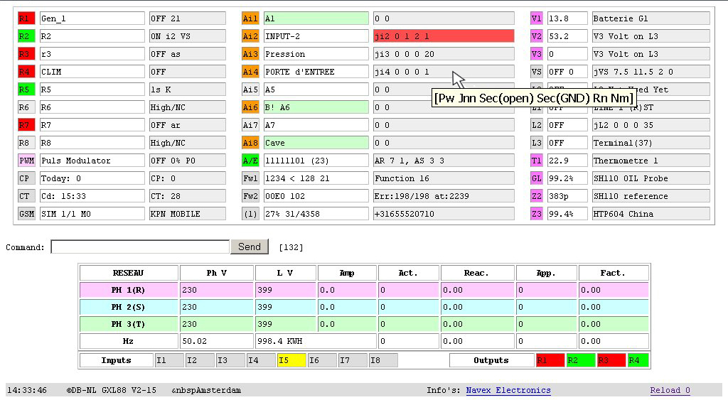
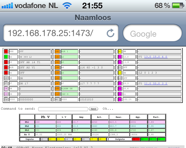
The GXL88 internally generates the page to be shown on the navigator of your choice. This because no program nor application needs to be installed to view the controller on any machine from anywhere. Here's a snapshot of the PC or mobile screen.
Developments were made with Firefox, SeeMonkey and Safari, but all navigators can be used with more or less ease (even the old Netscape!).

It is advised to ensure that the GSM SMS traffic with the controller works before changing the settings i via internet. If access through the Internet became impossible because of unforeseen or simply because a wrong configuration command is sent, an SMS command could easily restore the internet configuration if SMS communication works.

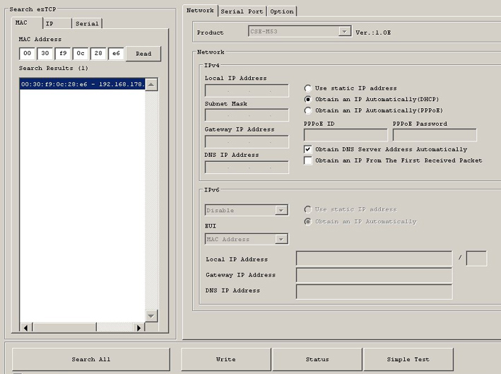
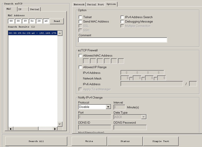
The built-in internet module will first be configured through the ez-manager that can view the parameters and change the settings. The program can be found here: ez-manager.  See also the web module documentation and a copy of the three standard configuration windows 1, 2 et 3.

Exmanager will show the LAN (=local) address assigned by the router. Force the router allways assign the same local address so that you allways can acces the controller locally. Type the the local address in your brouser: http://192.168.178.40:1453

[Code i] makes list the internet settings of the controller:

iCA 88.160.241.20:1425  GXL88 IP address and PORT after the ":" *
iSA www.nnnn.com/name   Address where GXL88 connect in client mode
iPN Page_Name           Name of the GXL88 internal internet page
iSL no_name            
GXL88 User name in client mode
iSW no_pass             Acces Password in client mode
iPR 0                   Optional, page auto-refresh (reload xx)
iPT 0                   To server connection Timeout
2x<32 3x<16 >10s >5s    Parameters length from ICA to IPT
iPB 7                  
GXL <=> M53 communication. 7=57600 default
I ON            Tell if internet active ON or i1 or OFF ex:[Pw i on]

Optional parameter Internet Controller Address will be assigned with the GXL88 internal internet module IP address when installed. This address, for example to http://53.123.234.50:1453, is the one to write into your browser address bar to get access to the graphic representation of the system and therefore, also be able to control it via the command line. This address will be readable at the router settings.

The Internet  Controller
Address parameter will be mostly used by the [Reload sec] command. So if ICA is not yet configured, just fill the address at the brouwser address bar and use the [Send] button  even with an empty command line! [Send] only uses the address bar as a destination.
As example and to set it via SMS [0000 ica 53.123.234.50:1425 i] The i will make you receive a control SMS back with the list i?. * ICA parameter is only needed for the navigator screen (bottom right) command " Reload 0 ".

iSA (optional) is the server address where the controller needs to connect to drop its measures or states when the internet module AND the controller are both configured in the client mode. T
his mode is simply the inverse of the normal mode where the controller server is interrogated by the browser as a client . The principle is the same as the GPRS mode that passes through the GSM network, but using the router and the Internet connection.
If necessary, an iSL identification name and iSW password can be configured to access the server. iPT will be the allowed time waiting for the connection to the server, before dropping or cancelling the transaction (Not used in mode i1 or i ON).

IPN (optional) the "Page_Name"
listed at above commande i is of real importance but still optional. It is the name of the internet page generated and sent by the GXL88 controller to your navigator screen.
Added to IP:Port/Page_Name all together makes the unique address where to connect to your controller. This page name, optional, will be "Page_Name" or "GXL88" by default if allready programmed (to check with command [0000 i]). Do not include any space in the name and use 15 alphanumeric characters maximum. The controller does differentiate lower and upper cases in "Page_Name", so it needs to be exactly spelled.

To remove the page name, send command [0000 ipn  ] and note here the standard space following the command name, but especially the second one effectively deleting the page name. This to check within the i? message received after command [0000 i] to the controller.
With none or deleted page name address just use IP:Port like; http://53.123.244.50:1425 to access the controller or from V2-17,
http://53.123.244.50:1425/-0000 ss to get a SMS like text back on your screen (see below #)

iPR may on some browsers automatically reload the page eg [0000 ipr 30] could refresh the page every 30 seconds. The parameter values will be displayed in the lower right just next to "Reload" which is 0 (zero) by default. Do not program it to too low, the minimum being about 10 for internet and less only on Local Area Network.
If by this method the connection has not been established, a blank page will be the result! Use then your browser back button to return to the last displayed page again and increase the value of the reload parameter IPR. However, it can best be left to 0 (zero) until we get used to the sometimes unexpected reactions of browser, controller and internet. Act calmly and do not click too fast and repeatedly on the reload or send button, because the internet and especially the controller need some time to do any command, especially when it is busy with the GSM traffic.

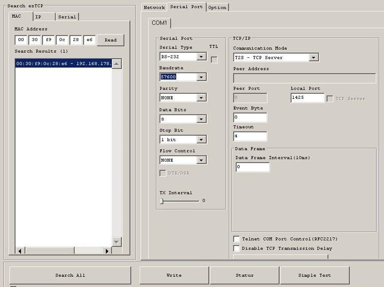
iPB is the "baud rate" parameter and sets the communication speeds between the controller microcontroller and the internet IP module. IPB 47 will be configured for a slow internet connection [Pw ipb 47] (9600B/s). The second [Pw IPB 7] (57K6) is the default setting and is the one to use for common ADSL connections. Finally [Pw ipb 3] (115K2) can be used, but does not always give good results via internet but can be used on LAN.
In all 3 cases we will locally configure the (M53 or else) Ip module via LAN first with ezmanager at tab "Serial Port / Baudrate" and after that  parameter iPB via SMS or PC. Make sure in any case that the SMS mode or PC mode is working in order to restore configurations that could unintentionally be altered.
Small difference: Try to connect with bad IP:port will return "site not found " and with correct IP:port but bad page name will return "connection reset".
The UTP, RJ45, network cable or whatever we call it, will be connected to the controller RJ45 connector that accepts and automatically detects both marked as crossover or patch, straight cable.
The LEDs of the RJ45 connector tells about the connection state to the router and shows an active connection. Amongst others, continuous green and yellow intermittent lighting means logged / recorded to the router. If both LEDs, green and yellow, stay lighted without intermittence, this means the connection is Active. Disconnect the cable and reconnect for a few seconds observing the LEDs which then also indicate the offline state and reconnect...

The web interface gives almost everything visible on a single screen at once and passing the mousse through a field adds more info at the tooltips. Nevertheless, some time will be necessary to get used to all the shown information. Easy enough, the command line will accept exactly the same syntax as the SMS or PC commands.
As seen above, pressing "Reload 0" requires the correct definition of the parameters iCA and optionally IPN. Button "Send" even with an empty command line will use the browser's address bar.
If the PMC is connected, the measurements will be updated after having reloaded the page with the "Reload" and not by the command "Send" unless of course the order is precisely Se, Sx or Si. The PMC is visible on the screen if ACM > 0 and its i/o if ACi >0. See the functions expert.

Internet and PC mode can not be used simultaneously on the GXL88. To resume the PC mode command [0000 i off] must be sent from the internet or SMS to the controller. The [0000 i on] sent by SMS or PC restore the internet mode. Make sure the controller is still accessible via SMS in order to unlock an unexpected situation especially when the manipulations are done remotely from far.

If necessary the optional Internet module (24x20mm only) will be plugged at its place in the controller. Be very careful to the insertion direction and notice the white dot on the top left side of the module and also on the controller board. This and other manipulations must be done with non-powered controller. Connecting the controller to the router via UTP cable makes this last automatically assign a local IP address to the controller internet module (DHCP) so that it will then be also accessible from the LAN with http:// Lanipadress:port/Page_Name.
The internet module assigned PORT, here 1425 for example via ezmanager must also be assigned in the router to be able to access the controleur from outside via internet with an address like: http://WEBipAddress/PORT/Page_name. See therefore the function port forwarding in your router.
To limit the supply power and consequently the controller's internal temperature, shown at T0 in menu G?, do not plug in the network module or, if it is already installed, unplug it when the internet is not going to be used on the controller. This module is not required when no LAN or Internet will ever be connected. Set also the internet parameter to Off via command [0000 i off] to the GXL88.

# A new function has been added from version V2-17
in order to solve differents cases of internet connection which will not give a correct graphic representation of the controller (like on ships with internet via satelite). We will then be able to directly use the address bar in command mode like http://WEBipAdresse/PORT/-Code (cmd) So for example http://53.123.244.50:1425/-0000 ss will make return the extanded status directly on the screen.
So if of course the internet function is active see [Code i on], writing ip/port/-0000 cmd i in the address bar will return the menu i after having executing the command(cmd). This on the screen itself via internet independament of sim mode. All commands are allowed and a sim is not required if the internet connection is stable. Graphical and/or textual representations can even be used together.
The -code (cmd) replaces the Page_name if there were any and is written after the /. Know that if the Internet is cut (or code i off) and the controller is in SIM 0 mode, it will only be accessible by the PC via its serial jack. Anyway, the Internet modes or PC and GSM are all compatible and both can work simultaneously (thus not the Internet mode and PC serial!). One can even restart the gsm connectivity in mode sim 0 with the command " Fg " (see F?) Or for more safety use the Internet mode with a sim with controller in SIM mode >0.


For Vn, Tn and Zn, a Warning can be sent, because all can have junctions with Low/High thresholds and also (< / >) inferior and superior edge points configured at which they can send Alerts. Both thresholds Low / High must of course be configured to different chosen values​ and generally with the alert (< / >) beyond the Low/High thresholds of the junction.

Alerts are messages sent when the programmed values for < (Low) and  > (High) edges or thresholds are exceeded. They are simply setup with the function name followed by the < and > parameters. So for the V1 example following, <11 and >14 volt, [0000 V1 11 14].
Same for Vn, Tn and  Zn that all can send alerts.
A received Alert SMS start with a)

Warning messages are optionally sent by the Junction functions (see just below) that can switch any output from almost any input. Warning will simply notify of a junction action when wanted, to any number on the number list N. A received Warning SMS will start with w)
Notice that the GXL88 SMS controller is able to sent both a Warning and an Alert message for the same event. This at same or different measured and programmed values.

The Alarm function, when activated with A=On, O+ or by the optionally connected switch "
button" will send an Alarm SMS message.
Alarm messages start with; !ALARM!

So, and
not to be confused at controller setup, beside status, infos and configuration messages received on request, we can get three kind of messages from the controller. Warnings, Alerts and Alarms.

Important to consider for a)lert and w)arning, when the thresholds, edges or trip values programmed at fields {JON} and {JOFF} of a Junction in order to automatically regulate a system (load, temperature, or other) and when a malfunction occurs, an alert will be sent when the alert thresholds < and > are configured beyond the threshold of the {junction}.

Please continue with the special functions
by functionality ranking here below or go back to the basic functions list.


J    Junctions.  Ji1 to Ji8  /  L0,1,2,3  /  JV1,2,3,S  /  JT1,2  /  JZ1,Z2 and Z3            

The "Junction" functions give you the possibility to link any input(s) or any event (Voltage, Temperature, Level changes and others) to any one or more output(s). These Junctions, soft but physical, add the "extended" functionality and flexibility of the GXL88 controller.
The most simple one for example, can switch an output relais On, Off or for a time lapse, depending on an Ain and/or a Ln input change, and others can force one or more output actions and optionally send a warning at programmables Vn, Tn, Zn threshold or edges values.

[Pw J?] returns an SMS that shortly explains the principles, [Pw JL] lists the active Junctions parameters, [Pw Js] lists the junction input delays for Ji1 to JL3 that uses seconds, and [Pw Jm] the unlock parameter for JV1 to JZ3 that use minutes
. [Pw JnnFx] forces execution!

A basic Junction has 5 fields:  [{Jnn} {JON} {JOFF} {JR} {JN}]

{Jnn}   The name of the junction Ji5, JV1, JL3, JT1, JZ2,,,
{JON}   Says what to do with {JR} if {JON} goes to level 1, On or Low
{JOFF}  What to do with {JR} if {JOFF} goes to level 0, OFF or High
{JR}    The Relais R1 to R8 to be eventually switched ON or OFF
{JN}    To which number (1 to 35) send the optional w)arning

We speak of 1/0 for inputs Ai1 to Ai8, On/Off for inputs L0, L1, L2, L3
and LOW and HIGH for the inputs from V1,2,3,s, T1,2 and Z1,2,3.


[Pw JL] lists active Junction parameters (values are examples).

J On/Off R N        {JON} {JOFF} {JR} {JN}
i1 0 0 1 3          Input Ai1, R1 Off on any change warning to N3
i7 0 0 0 1          Only Warning to N1 when Ai7 changes level
L2 -1 1 1 0         No R1 change when L2 On; R1 ON when L2 to Off
V1 11.0 13.0 4 5    R4 On If BATT <11, Off If >13, Warning to N5
VS 1 1 0 4          Grid ADAPTOR, warning to N4, no switching R=0
T1 19.0 21.4 3 0    Temp. R3 On If <19, Off If >21.4, no Warning
T2 3.0 38.0 3 1     Temperature Warning if below 3° and above 38°
Z1 5.0% 95.0% 4 33  Tank Level R4 On <5%, Off >95%, Warning to N33
Pw JLL              Only active listed, use JLL if more to list!

Jn s s R N          [Pw JLL] starts the listing SMS from J10=JL1
L2 -1 1 1 0         From Ai1 to L3 {-1}=No R change. 1 is just ON
V1 11.0 13.0 5 0    Only R5 switches on treshold, no Warning if 0
T1 29.0 22.0 3 0    {Inverted} keep cool with R3, No Warning!
T2 -15.0 -10.0 3 0  Relais R3 On if <-15 and Off when >-10, no w)
Z1 5.0% 95.0% 14 0  R4 OFF if <5%, ON >95%. R=Not R if offset 10!
Z2 45.0% 66.0% 12 0 R2 OFF if <45%, ON >66%. R12 = R2 inverted
Z3 3.3 99.9 0 0     No switching no warnings, values are idles

Ji1-Ji8. As an example, the junction command [Pw Ji3 1 0 4 2] to the controller will set the output relay R4 On when the level of input Ai3 rises from Low GND to High level, it will stop it when passing High to Low again, and in both cases it will send an SMS warning to the number programmed at N2  in the number list. See Js below if a delay is needed before Ai3 changes trigger the junction.
If the alarm function is active (
when A On or O+) on Ai1 to Ai8 inputs and an !ALARM! message is not wanted together with an input junction, simply reset the input delay to zero. So here [Pw A3 0] disables the alarm for Ai3, but leaves junction Ai3 active.

[Pw Ji3 600 0 4 0] makes set R4 On for 10 mn for Ai3 to High and stops when Ai3 go Low again. No SMS
[Pw Ji3 0 10 2 0] makes reset R2 to OFF when Ai3 goes to High and sets it On for 10 sec if low. No SMS
[Pw Ji8 -1 -1 4 10 Ji8s 0 180 N10 <NumberAtN10] will only make send a warning to number N10 in list when input Ai8 goes to Low level for 3nm minimum.
R4 will not be switched because for the first 12 junctions from Ji1 to JL3, -1 specifies no output change!

Another example to try. If we configure Ji5 and change input Ai5 to an output (with A5 to zero see R?) with command [0000 ji5 1 0 3 0 a5 0 r5 0] any change on R5 will be copied on R3.

From any {Jnn} Ji1 to Ji8 and L0 to L3 fields {JON(input goes from 0 to 1)} and {JOFF(input goes from 1 to 0)} are both capable to switch an output {JR} ON or OFF because of a corresponding {Jnn} input level change.

From Ji1 to JL3, field {JON} says what to do with {JR} when {Jnn} goes from 0 to 1 and to ON for JLn.
From Ji1 to JL3, field {JOFF} says what to do with {JR} when {Jnn} goes from 1 to 0 and to OFF for JLn.
        We can also speak of ON / 1 and OFF / 0 for L0, L1, L2 and L3.

So the two
{JON} and {JOFF} fields will have 1 of the 4 the commutation commands.
        -Switched On if {1} or for a time lapse {On up to 65K5 sec}.
        -Left unchanged when
{-1} and switched Off if field say {0}.

Command [Pw JVS 10.0 11.0 3 17] for example will configure the JVS junction. {R3} will be set ON by power failure and stopped when the line voltage returns, that will give 12V again on VS via the ADAPTOR. Warning is sent in both cases to the number at N17 in the list.
For this, the output of the delivered adaptor 240VAC to 12VDC will be connected at VS / ADAPTOR input ( 29+ ) and ( 30- ) and plugged in the main grid power.

Junctions Ji1 to JL3 also have configurable input delays for both 1/ON or 0/OFF level changes.
So as an example, we want to wait 30 seconds before turning on a generator running via R3 in the event of a grid power failure (off) and wait 2 minutes before stop after the grid wall power is restored (On). We will use L1 input connected with 12V positive at (35) and negative at any GND common connection and junction JL1. Vs already having ADAPTOR connected could do exactly same with junction JVS.
We configure separatly or all at once the delays, junction, stop JVS and write number if a warning is wanted:
[Pw JL1S 120 30 JL1 0 1 3 8 JVS 10.0 11.0 0 0 N8 YourMobileNumber] with, as always, 1 space character to  separate all the command fields.

JS  INPUT DELAYS are programmed in seconds            

[Pw JS] shows delays for junctions Ai1 to Ai8 and JL0 to JL3.

0-1 1-0      Level change at input (0 to 1) (1 to 0) 
i1 5 0       INPUT Delay de 5 sec for 0 to 1.
i2 0 180     3mn before execution of Ji2 when 1 to 0.
i3 0 0       0 0 no Input delay...
i4 240 60    Ji4, 4mn for Low to High, 1mn High To Low
i5 0 0      
i6 0 0       (0 to 1) and (1 to 0) for Ji1 to Ji8
i7 0 0       also(Off to ON) (On to Off) for L0 to L3
i8 0 0             
L0 0 0       Internal, reserved for now
L1 120 30    120s when to ON and 30s for L1 to Off
L2 180 0     Wait 3mn before JL2 execute when L2 OFF to ON
L3 0 100     0= no delay. 100s before execute L3 On to OFF
Pw JnnS S S  JnnS use SECONDS 0 to 250!

For example, command
[Pw JL1 -1 3600 1 10 JL1S 0 40] could set up a junction between L1 input and R1 that will activate the relay for an hour and send a warning to N10 in the number list, when the voltage disappears from the input L1 for at least 40s .

While (as seen above), the fields {JON} and {JOFF} of Ji1 to Ji8 and L0 to L3 indicate what to do with outputs when Jnn simply changes level 0/1 or ON/OFF, for JV1 to JVS,  JT1 / 2 and JZ1 to JZ3 they will indicate the threshold or edges value at which the output will be switched.
Therefore from JV1 to JZ3 , Junction fields:
{JON} is the LOW threshold value who will command the output {JR} ON
{JOFF} the HIGH threshold value above which {JR} will be switched OFF

So, in a JV1 to Z3 junction, an Output {JR} can switch ON when the input becomes LOWER than {JON} and switch OFF when becoming HIGHER than {JOFF}, both programmed threshold or edge parameters.
Like above, none of the fields are mandatory. Furthermore and as shown below, the threshold values for
{JON} and {JOFF} can simply be inverted as well as the {JR} cycle. From JV1 to JZ3 and Unlock timing, that will reforce the junction, can be setup.

[Pw JV1 11.6 14.1 3 0] as example enables a Junction between the voltmeter V1 BATT (31) and output R3. So when the battery voltage becomes lower than 11.6 Volt, output {R3} is switched ON and above 14.1 Volt it is switched OFF.
This junction can give a simple but effective charge control on the outputs {Rn} , which are all equipped with a relay of 10 Ampères.
No warning is needed, so {JN} is left at zero value or else, {JN} will point to the number position of the list where to send the warning...

(Password {JT1} {LOW_Temperature} {HIGH_Temperature} {JR} {JN}
This can setup a heater junction between the (delivered) Thermometer sensors T1 and an output {JR}. This gives a simple thermostatic control on T1(39) and/or T2(47) no warning will be needed, but the function Tn < > can be set to gives anomalies alert (see T?}...
Thus, here as an example the command:
[Pw Jt1 18.5 20.5 3 0 T1 15.5 23.3]

[Pw JZ1 5 95 0 11] Can make send a warning at N11 if lower than 5% and higher than 95% level (no JR).
[Pw JZ2 10 90 2 0] Can start a pump on R2 below 5%, fill the tank to 90% and stop (no warning JN=0).
[Pw JZ3 5 95 12 18] Can make switch a pump to empty the tank when above 95% and send a warning to the number at N18. R2 will stop the pump when the level comes below 5%. Note here that the field {JR} has an offset 10 so that the commutation cycle is inverted.

[Pw JT2 32 22 4 0] R4 ON above 32°C and stop below 22°C. This could be used for some cooling device which is the opposite to the T1 heater junction just above. So {JON} and {JOFF} can also be inverted!
[Pw JZ3 45 70 0 25] There is no switching when {JR}=0), only a warning for above 70% because N25 is ">NUMBER". As seen before at N? , when a number is preceded by < or > it will only send for an Off/0/Low or On/1/High event.

[0000 JV2 47 56 2 0 V2 46 58] configures a junction between input V2 and output R2. If the voltage V2 decreases below the setting of {JON} (47V) at input V2 (33), R2 is then switched to ON and on the other hand it will be swiched OFF when the voltage at the input increases above the setting of {JOFF} ( 56V). No warning is needed here when just switching a charger On and Off.
If the charger does not work well (or that othetors also order  switch R2) and that the voltage drops < 46V or rises > 58V, an Alert will be sent to N1 (and to a second number depending on parameter V1N) by the V1 < > fonction. This gives a good control of the charger and the output...

A Junction Warning SMS message will look like:

w) Z1/GL(43)      Shows Z1 alias, here GL for Gauge Level
HIGH = 80.1       w) for warning. Actual measured value
Ai: 11111101      This line only when i1 to i8 junction
JUNCTION JZ1      Specifies JUNCTION not a)lert or !Alarm!
10.0 80.0 2 0*    Actual jz1 junction settings. (*see below)
SH110 OIL Probe   Name of the FUNCTION (not the alias)
JnnS 10 20        Optional sec. junction delay if i1 to L3
JZ1M 1            Optional Mn junction delay if V1 to Z3
R2(on)=OFF        Output R's previous state and now switched
for: 5s           For how long, if timing value, when I1 to L3
Use Pw s, J?, JL  Suggests commands related to Junction
07:10 Amsterdam   Controller time at warning and name/location

Or for junction Ji4 for example:

w) PORTE d'ENTREE   A/i4(24) =1    Ai: 11111101   JUNCTION Ji4
0 0 0 1             Ji4S 5 5       R0(off)=OFF    etc...

Or for Junction JVS Voltage Supply at ADAPTOR:

w) VS/adap(29)      LOW = 6.8      JUNCTION JVS   7.5 11.5 2 1
WAS GXL83x AC       JVSM 0         R2(off)=ON     etc...

Junction field {JR} can first make switch an output and field {JN} vectors/points to the position where to find the number to send the optional w)arning (see N?). But when a command and not a number is written there, a following local command can be executed.
So
if the above example says 24 and not 0* at {JN} and we programme N24 with [Pw N24 =R4 180 s+31],  junction JZ1 will first switch R2 OFF(bcs >80%), R4 for 180 seconds (cmd at N24) and finally make send a status ss to number N1 after 31 seconds. So one trigger can switch more than one output.


JM  Unlock timing can be setup for junction JV1  to JZ3.          

Unlock timing is programmed in minutes and is accounted for both {Low} and {High} Input level event. Unlock timing can force a junction to trigger again and again after 0 to 250 minutes if the previous junction action did not change anything and when the Low-High threshold values are still outside de programmed working window, which is of course between de {Low} and {High} thresholds. When left unused (JnnM 0), the junction normally executes once passing the programmed triggering level values (threshold) {Low} and/or {High}.
So in case we want  to
switch a pump that begins to fill a tank at 5%, stops it at 95% level and receive a warning on N18 when doing so, we will program a junction with [Pw JZn 5 95 3 18 JZnM 10 N18 NumberToWarn] where n is Z1, 2 or 3 and 10 is the wanted Unlock delay written in minutes.

The above JZnM settings will reforce the JZn Junction each following 10 minutes. Try to start the pump again and warn N18 again ONLY if the level is still below 5% AND that there is a real R3 switching (because R3 was switched off for whatever reason).
On the contrary, if the tank is still above 95%, R3 will be checked again every 10 mn and the junction will do nothing if R3 is OFF. If not, R3 will be switched Off and a
warning will be sent again.
For even more security we could also setup the Zn < > function outside the junction edges like 4% and 96% and get an Alert message when the level exceeds these alert limits. To setup an Alert, use [Pw Zn 4 96] as an example.
Remember that junctions send warnings and < > functions send Alerts,


[Pw Jm] lists the junction Unlock delays for JV1 to JZ3.

nn Mm        Name / Minutes. Same delay for {JON} and {JOFF}
V1 0         Unlock delay for JV1 (31)+ Batt 12V
V2 5         For JV2(33)± voltmeter to ±90V Direct current!
V3 0         For JV3(37)+ (Second batterie input? or L3)
VS 0         For JVS. Adaptor 240/12Vdv at (29)+ and (30)-
T1 5         Unlock delay for JT1 at (39)T (signal)
Z1 10        Unlock delay for JZ1 (gauge / Thermo / Volt etc)
Z2 0         Unlock delay for JZ2 (gauge / Thermo / Volt etc)
Z3 1         for JZ3 (gauge / Thermo etc).. See also Z?
JnnM MMM     JnnM USE MINUTES 0 to 250!

The use of the PC program or, even better, via LAN will make a simulation + evaluation of several combinations much easier.

Added Options for junctions switching.          

Two software junctions J21 and J22 were added to the Junctions 1(Ji1) to 20(JZ3). Any of the 20 first junctions can have the {JN} field offset by a value of 100, so that they do not vector anymore to the number list, but to another junction. Any junction having field {JN} at 121 or 122 will point to these software junctions J21 and J22 that are not connected to an output like the others...
These two junctions, J20 and J21 are configurable just the same way as the 12 first ones and can have {JON} and {JOFF} at  -1 for no  change, 0 for OFF, 1 for ON and SEC for seconds Timing, both fields telling what to do with field {JR}.

Any junction trigger can make execute another junction by simply jumping to it when the {JN} vector is in range of 101 to 122 and so also to an used or unused one (command JL will show which junctions are active)!
A repetitive action as when a junction points to itself will escape after 5 times. To make it easy, please try the basic one step Junctions at first...

 In this example we configure JLn where n can be 0 to 3 with a 12V ADAPTOR connected to it.

[Pw jlns 0 60]      Waits 1mn delay for input ON to Off
[Pw jLn 0 1 2 121]  R2 OFF if Ln On, ON if Ln to Off. Next J21
[Pw j21 -1 30 4 18] Next: R4 ON 30s when Ln to Off, Warn N18

Fields {JON} and {JOFF} to -1 always discard any action on {JR}and thus, as here above, if Ln goes from Off to ON {JON} will keep R4 as it was. To make it also switch when Ln goes from Off to ON just fill in field {JON}else than -1. The junction warning is sent by last {JN} if not 0.

************************************************************************************************
Un champs {JON} ou {JOFF} à -1 annule toute action sur {JR} et que donc ici, Ln à ON laissera R4 inchangé. Pour également avoir une action sur {JR} quand Ln passe de Off à On, remplir le champ {JON} différent de -1. L'avertissement est envoyé par la dernière jonction si {JN} n'est pas 0.

Donc l'exemple suivant:
[0000 Jv1 11 13 2 121 j21 600 -1 1 122 J22 0 0 3 1 jl]

Fera enclencher R2 quand la tension à l'entrée B1/V1(31) descendra au dessous de 11 Volt, mettre R1 en marche pour 10mn et eteindra R3 au cas ou il serait enclenché.
R2 s'arrête si V1 monte à plus de 13 volt R1 n'est pas changé (à cause du -1) et R3 s'éteindra au cas ou il était enclenché.
Notez que l'action de passer à 13 Volt débloque la limite basse de jV1 qui pourra de fait à nouveau fonctionner.
************************************************************************************************

JnnF1 JnnF0   Force/test the junction execution.           

To control the configuration performed on the junction, it is possible to force their execution by simulating a change. We first take the most simple junction example and configure the junction Ji4 with [0000 Ji4 0 0 0 1] so to get a warning to N1 for any input change 0 or 1 of Ai4. Now we can force execution by simulating 0 level on Ai4 with command [0000 Ji4F0] or level 1 with [0000 Ji4F1].
For Ji1 to Ji8 the simulation works both directions 0 or 1 independently of the input level or its corresponding Js delay. For the other, the junction condition needs to be true and the junction should have already worked.

So for [Pw Ji2 0 1 2 1], command [Pw Ji2F0] simulates a low level 0/GND at Ai2 input and so forces junction Ji2 to switch R2 On. When not, it is already On of course. On the contrary, command [Pw Ji2F1] will force junction Ji2 to stop relay R2, because fields {JON } = 0 which means Off or 0.
So here again clearly, 1 at the input activates the field {JON} and 0 activates the field {JOFF} of the junction function.

For JV1 to JZ3, JnnF1 activates field {JON} and JnnF0 activates field {JOFF}. To simulate the junction VS, the voltmeter at box input (29)+ (30)-, send JVSF1 or JVSF0. If, of course, the junction has already been configured as for example like [JVS 9.9 11.1 0 1].


K   Interval timing on Rn.    [Pw I?] gives the details.          
 
One of the four relay Rn outputs can be used as a flashing, Klignoteur in Flemish and Dutch (the GXLxx were designed in The Netherlands).  One of the
4 Ai5 to AI8 inputs can also be used when the input is configured as an output. See therefore at menu R.

[Pw K3 40 3600] turns on the R3 output for 40 seconds , stops , waits 3600 (1H) and restarts again for 40s and so on, until the [Pw K0 0 0] command which resets the function to idles state or another R or timing value like
[Pw K4 40 3600].
Note that when the klignoteur is running, a status will show the remaining time ON and remaining time Off next to the corresponding output. The cycle starts with putting the relay to On. Do not choose too short flashing time in order to spare the mechanical relay output!

The maximum delay of kr On or Off can be up to 65k6s maximum, where 65500 seconds will make a time laps > to 18H. If the function k is used on one of the 4 inputs AI5 to Ai8 configured as an output, the On/Off time can be reduced to a minimum of 1 second.

 Take the case of input Ai5 transformed into R5 output as seen in R?. So the entry delay is set to 0 by sending the [Pw A5 0 K5 4 8]. This would make the output R5 4 seconds On  (level 1) and 8 seconds OFF (level 0).
As a test, a
10 mm "low power" LED (we can provide the LED for free) can be connected directly to AI5 and GND connections on the right. Then send the command [Pw A5 0 K5 1 1] to have one sec On and one sec Off. If the LED does not flash, just exchange the two connections on Ai5 and GND.


M  Monitor audio   [Pw M?] explains the function.          

The internal microphone at position (52) of the controller box (do not push anything in there!) can automatically be activated during an alarm so that the controller can make a voice (any fixed or mobile) phone call by itself to the outside. The MIC function can also be setup for auto answer, so that the controller replies on normal phone call. Review also N at ** for more infos.

For example, first send the [Pw M2 s] to make the controller auto answer a call (the s, optional, will return a status message and should be visible as M2 in the status
). After that, dial the controller's SIM card number like a normal phone and you will be able to hear around after 2 rings.
Values of M ​​are valid from 1 to 5, but rather choose 2 or 3. Hang up to end the call, recall or clear the function by [Pw M0] [Pw M9]. The MIC will deactivate itself at HH:59 +1 (so each new hours). [Pw s] or [Pw m] will show the actual configuration.

M set to 9, [Pw M9], makes the controller send back a Status short message when called. This message is sent to the first number in the list (position N1) after two rings. To get  the status message, when M9, just normally (voice) call the controller SIM number. The call can be terminated when the third ring is heard.

A call request to the controller is also possible by command ! and so if we send [0000 !NumberToBeCalled], the controller will then dial the "NumberToBeCalled" and so make a phone call to any phone with open mic. Just hang up to complete or the controller will do so itself after a certain time. [0000 !N8] could do the same with the number at position N8 in the list. (see at !)


T   Temperature Alert and setup for T1 and T2.     list

The thermometer function can automatically send an alert when the temperature falls below or above the programmed edges < and >. These edges, thresholds or limits, as we prefere to call them, are programmed by the command [Pw T1 2.2 37.5] for example. The alert will be sent by default to N1 (changeable), but a second alert number could be programmed by [Pw T1N 13] for example, which makes send the alert to the number written at position N13 in the list of numbers.
As seen at J, we use function JT1 when an Output needs to be switched if the temperature exceeds programmed thresholds.
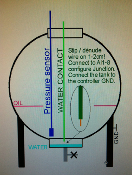
A temperature Alert will look like:

a) T1 Temp(39)!
     Who is giving the Alert. Box position (39)
HIGH = 37.6         Problem! Temperature should never be so HIGH
LOW limit: 2.2      Programmed inferior Temperature edge <
HIGH limit: 37.5    Programmed superior Temperature edge >
T1o 0 T1N 13        T1 offset and possible second ALERT number
Not from: JT1       Specifies NOT Junction JT1 w) BUT Alert a)
0 0 0 0             Eventual JT1 Junction Configuration
Thermometer 1       The name of the Function T1. See at e?
Pw s, T? J?         Recommended cmds if message not obvious
10:36 Name/Loc
      Controller time at Alert + Name/location
                    Junction and Function; not to be confused!

T1 is the 0-95 degrees delivered thermometer connected to GND (38), Signal (39)T and +5volt positive at (40) or simply plug in at same connections without mistake SVP. The same temperature sensor can also be connected to the position T2 / Z3 of the box when Z3 is configured to read a thermometer type 5 (see Z3 Type at menu Z).

T2 is the optional
-40 +125° (degrees Celcius) digital sensor (or same as T1 0-95° thermometer) that can be connected at T2/Z3.
Due to the fact that input Z1, Z2 and Z3 can be configurred to receive differents kind of sensors, Up to 4 thermometers can be connected together to the GXL88. Z1 and Z2 can then be renamed to T3 and T4 and Z3 as T2 (see command [
Pw e]).
When T1 to T4 can be connected to long wires, GXL88 also have and internal T0 thermometer sensor that give the controller inside temperature at G menu when using command [
Pw g].
Use command T2+ to make list the optional T2 in the status and Tn- to remove it from the status listing.

Cmd [Pw T] shows the temperature functions T1/2 infos.

Pw Tn L H         The way to setup the function  T1 < >
T1 20.1 2.2 37.5  Actual T1 temperature, < inferior and > superior
T2 4.4 -0.5 7.0   Actual T2 temperature, < inferior and > superior
<T> SMS N1        Alert to N1 if < (inferior) or > (superior)
T1o -0.1 N 13     T1 offset and second Alert number (N1 to N35)
T2o 0 N 0         T2 offset and second Alert number (N1 to N35)
Pw Tno (o)        [Code Tno -0.1] the way to program T1/2 offset
Pw TnN (N)        [Code T1N 13] the way to program second Alert
See; JTn Tn-/+    JT1+JT2 Output+Alert. Added/Removed to/from status
T1+ T2-           [Pw T1+] or [Pw T2-] to/from status
</>=0 No SMS!     No Alert if any < or > = zer0

Sensor T1 gives 10mV/degrees centigrade and is supplied with 5V/regulated by the controller output at box terminal (40). It is preferred to use a shielded wire when the sensor is deported with more then 3 meters cable. In all cases, the cables of the Vn, Tn and Zn probes must always be as far as possible from other wires that can induce a parasitic current such as antenna and 220/380 voltage especially when high current flows.
Depending installation type and situations, it is not always necessary to commun connect GND shielding to earth ground. In case of trouble and because grounding to earth implicates many complex factors, an electrician should better be asked to discuss the
matter.

Testing the thermometer function: At 10mV/1° and for 18° one will measure 0.010 x 18 = 0.180V or 180mV. The measurement will be made ​​with a digital voltmeter between the terminals of the controller (38)- and (39)T. Send then [Code T] to the controller which then have to indicate 18° ± the offset. The offset T1o will be used to calibrate or scale T1
Up/Down, but will normally remain to zer0.

Easy electrical test and control of the temperature sensor. Connect a 4.5V battery with Negative (-) to the left pin and + 4.5V to the right + pin of the thermometer probe or sensor. Then measure the voltage between the left pin (-) and the signal (39)T at the middle. The measurement reading must match 10mV by degrees Celcius if the thermometer is in good condition. And so 22° should give 220mV...
Always be careful with the connections, if a doubt remains reread the manual or ask a technician before burning some things!
If the controller is powered by a battery (31)+ (32)- and/or by (34)- (37)+ by a second battery, and/or via a grid ADAPTOR at (29)+ the voltage should not go below 8 volts to ensure correct temperature
measurement.

And finally a simple example of T1 configuration: Already Insert the probe at (38) (39) (40) from the right side! Then program the thresholds T1, N1 T1N by sending [0000 N1 YourNumber T1N (0 to 35) T1 15.5 25 T?] To the controller via SMS, PC or the Web.
Heating
the probe with your finger tips over 25° will Alert N1 and eventually the second Alert number at T1N. Note here again that < > Alerts are independent of Junction warnings that could also have been configured.
For T2 conneted to terminals (46)(47)(48) we will send command T2+ or Z3+ to make it visible on the status message S and asign the offset as needed.
If we use the
the -40+95° T6 type thermo probe at Z3/T2 the place, we will send [0000 T2+ T2o -0.2 Z3M 0/6/0 ss]. As a control we will know that Type T6 give about 2.90 volt output a 20° Celcius and that the voltage change with 10mV/K. We connect it with Brown=GND=(46) White=Signal=(47) and Green, 5V supply comming out the controller at terminal (48).
For this probe -40/95°, Type 6 offset 0 is same as using type 5 with offset -290. So use this when the GXL88 firmware version do not support type 6. Type 6 is supported from version 2-17. (Feb 2017 zie menu F?)


V      Voltage Alert and setup for V1, V2, V3 and VS            

The voltmeter function can automatically send you an Alert SMS when the voltage falls below or above the programmed edges < and >. As before, these edges, thresholds or limits, could be, for example, programmed by the command [Pw V1 11.2 14.0].

The alert will be sent automatically to N1 by default (changeable) but if necessary, a second alert number can be programmed by [Pw V1N 15] for example. This would make send the second alert to the number written at
position N15 in the list of numbers.
As seen at J, we use function JV1 when an Output(s) needs to be switched when the voltage will exceed programmed edges.

A Voltage Alert Vn < > to your mobile will show:

a) V1 Batt(31)!   Which one is giving the Alert. And box position (31)
HIGH = 14.1       Volt at V1 input! HIGH so Alert
Low limit; 11.2   Programmed LOW voltage edge <
High limit; 14.0  Programmed HIGH voltage edge >
V1o 0 V1N 15      V1 offset and possible second ALERT number
Not from: JV1     Specify
a)lert not Junction w)arning
0 0 0 0           Eventual JV1 Junction Configuration
Battery G-1       The name of the Function V1. See at e?
Pw s, T? J?       Commands to see when message not obvious!
10:36 Name/Loc
    Controller time at Alert + Name/location
         
The V1 voltmeter will reflect the voltage measured at box terminal (31)+ and (32)- negative and is generally where the 12V G1 generator +BATT is connected. V1 will give the condition of the said 12V battery. In a minimal controller configuration, a backup battery can power the controller via the V1 input on the event of ADAPTOR (VS) power failure. 16V maximum to this entry anyways.

The voltmeter V2 will measure an external voltage up to ±80V DC applied to box connector (33). Generally used to measure a battery pack of 24 or 48 volts. If the battery pack is grounded by its positive pole, then connect the -batt at (33). The pole connected to earth must then be connected at (34)  the
point GND of the controller (32) or (30) will do as well. V2 measure negatives AND positive voltage.
V2 also
internally mesure the voltage applied at (11) and (12) for the internal 48/15 converter. So do not connect V2 at (33) if (11) and (12) are connected.

Input V3, also a voltmeter, is shared with L3 entry at connection (37) of the controller case. When the installation has two generators, V3 will be the input for the battery+ G2. In other cases we can supply V3 via a same
12V ADAPTOR as below or with any DC source, making sure not to exceed 16V maximum!

ADAPTOR Input at (29)+ or positive, is also the voltmeter VS (Voltage Supply). This input is normally powered via the network grid power via the delivered 240 to 12Vdc power supply adaptor. But another source of 12V could be fed at Vs at position  (29)+ for positive and (30)- for negative. Maximum 15V to this entry one way or another.

Any of V1, VS and V3 or two of them and also all together will standard feed the controller but not V2 that is only a voltmeter. All GND's are all connected together internally and also need to be connected externally when some device(s) need to be powered with these leads, because no high current must be flowing through the controller GND circuitry, being the measure reference level. See GXL88 supply for details.

Command [Pw v?] will show the voltmeter function infos

Pw V1 L H           Syntax to setup V1 < > edges
V1 12.2 11.2 14.0   Actual Volt, V1 < > edges
V2 53.2 47.0 56.5   Actual Volt, V2 < > edges
V3 12.3 11.1 0      Actual Volt, no Alert for < > at 0
VS 12.0 10.5 11.5   Actuel Volt, < > for VS Alert to N1
<V> SMS N1          Alert to N1 if < or >
V1o -0.2 N 15       Offset. [Pw V1o -0.2 N 15] alert to N15
V2o 0 N 10          Offset. [Pw V2o 0 N 10] and second Alert
V3o 0 N 0           V3/L3. No offset nor second Alert wanted
VSo 0 N 3           Offset = 0 and second Alert to number at N3
Pw Vno o VnN N      ex: [Code Vno 0.2] , [Code VnN 15]

So the 4 voltmeter functions have a minimum < and maximum > configurable threshold at which, when exceeded, an alert will be sent to number pointer by N1 and if wanted to a second number from the list. As above for example V1 to N15.
An Offset o can also be
separately programmed to each voltmeter whether the voltage is deemed inaccurate or if one wants to shift the measurement result ...

Voltmeters V1, V2, V3 and VS can all operate outputs and
send Junction warning messages when corresponding junctions JV1, JV2, JV3 and JVS are configurated as shown in J?.
To configure the Junction JV1 without warning and at the same time a security alert < >, send for example the following command to the controller [Pw JV1 11.8 13.8 3 0 V1 11.2 14.4 V1o 0 V1N 15]. The junction will switch {R3} ON below 11.8V and OFF above
13.8V. If then after that, the voltage still rises or drops outside the edges of V1 < >, an Alert will be given firstly at N1 in list and secondly to the number pointer by N15.
Please note again here the value of alert < is inferior to Junction field {JON} and that value of > is s
uperior to the Junction field  {JOFF}.

As for the other functions, when a voltmeter is not in use, it can be removed from the status message with [Pw Vn-] (n for 1,2,3 or S). It remains in the message V?. We can put it back to the status with command [Pw Vn+].


Z1 Z2 Z3 
   Multipurpose sensors inputs. 
          

These inputs accept various types of analog sensors such as pressure sensors , temperature etc. Inputs being separately configurable, a thermometer or an additional pressure sensor is easily added. The analog inputs directly accept a signal of 0-5 volts on the measuring inputs and up to three probes can be connected.
Inputs Z1Z2 and Z3 may be renamed in order to recognize the function, T2, GL, Vt, Th, G3, etc could then be visible at the status message. Unused Zn fuctions will be removed or added from/to the status if Zn- or Zn+.

Below you will find a brief description of the most common probes. However, installation and connection of a pressure sensor probe usually requires some expertise and should best be done by a specialist in the matter. Special sensors for voltage, current, humidity and other are provided on request with their respective documentation.

Pressure sensors type gauge or gage are compensated for atmospheric pressure variation. For the immersible type this is done with a  fine capillary tube passing through the
connection cable. The power source 12/15V is made at the controller (45)+ or another external low power but stabilized source. Generally they have 3 wire connections, 0 = GND, Signal = Zn and supply 12/15V or more. Up to 3 pressure sensors can be connected directly to de GXL88! (Optionally 4 if T1 is not used).
The gauge type pressure sensors are referenced to ambient pressure, the measure gives
thus the absolute pressure -(minus) the atmospheric pressure. So if possible, use the Gauge type that does not require a second atmospheric reference sensor...

For a 0 to 5V full range output signal, 100% of the probe measuring window can be read. For a still usable 0-10V output sensor,
only 50% of the range will be read, because double pressure will be needed to reach the 10V for the maximum range...

Sensor choice is of fist importance (see other equipment from us) and must be related to the height of the tank. The maximum height in cm liquid equals about the scale of the probe for millibar for water and will give the
greatest resolution and consequently more precision*. We do not sell probes, but can recommend a dealer.
Recommended are quality sensors (0-5V analog) that can read the level to 0.2% when well matched to the tank. A type "immersion" IMPRESS SENSOR LTD (UK) or HOLYKELL IMSL (HK) HTP604 and other to be screwed on the
(1/4 inch) piping from SENSOR TECHNICS GmbH in Germany, but there are of course many other...

*Be warned anyway for resellers using a standard measuring diaphragm and adapting the output signal window (here 0-5V) for only half of the scale. The sensor is then only used at half its capacity, reducing strongly the resolution of the probe. So for a 100mBar tank the sensor diaphragm must be designed for 0 to 100mBar.

Absolute pressure sensors such as for example the type SH110 power supplied with 5V by the controller or another source. This type of sensor is not compensated for atmospheric pressure variation and therefore requires a second
reference sensor reading the air pressure, so that the GXL88 after calculation, produces the tank level value. Here also possibly with 5V at 100% full and 0 when about empty. One tank with 2 SH110 or 2 tanks can be  measured on Z1, Z2 and Z3, with two SH110 and one for the reference.
Absolute pressure sensors are referenced to vacum. The datas are equal to the fluid pressure(high) + the atmospheric pressure .

Pressure sensors Type 4-20mA. These probes, temperature and atmospheric pressure compensated will be chosen* so that the maximum level of the tank filled corresponds to about 20mA. The probe can be powered at the controller (45)+ via the internal converter or with an external 15 to 24V power source. Internal corresponding jumpers 1 and/or 2 (next to the middle red/green LED) need to be inserted for 4-20mA probes.  Up to 2 tanks can be measured with 4-20mA probes and one more 0-5/10V at Z3.
Be aware that 4-20mA sensors consume more current than the 20mA, especially with TWO 4-20mA probes. So we have to be sure that
the used/installed internal converter is able to output the TOTAL power of the 2 or 3 probes or an external power supply will be needed. Furthermore, 12V from a battery will likely, but depending of its type, not be enough to feed a 4-20mA pressure probe at full range.

Thermometer
probe Type 5 / T1. Thermometer probes, similar to the standard one T1 0-95° and powered by the controller with 4V to 12V (like the 5V output at (40)+ and (48)+), can be connected to the inputs Z1, Z2 and Z3. Moreover, Z3/T2 accepts direct connections of a standard T1 thermometer probe at (46)- (47)T and (48)+.
Beware of (48)+ which is a +5V output to power temperature or other
sensors. Up to 4 standard thermometers can be connected to the GXL88!

Probes thermometer type 6 and 7. Other thermometer can be connected to the inputs Z1, Z2 and Z3 and be powered via the
controller's power pin (48)+ for 5V or (45)+ for 12V. They are also simply powered by an external power supply, because these thermometers type 4, 5 and 7 are not ratiometric sensors (where the output signal voltage is proportional to the supply voltage).
Z1, Z2 and Z3 multipurpose inputs accept special thermometers type 6 -40 +95° and ±2.5V type 7
Type 6 mesure from
-40 to +95° avec offset ±0. As a control, Type 6 probe show about 2,90 Volt output voltage at 20°. They will be connected with Brown=GNG=(46) , White=Signal=(47) Green=Supply=+5V=(terminal 48) when used at T2/Z3 input.
Probe Type 7 (thermo or else) gives 0 reading at about 2.50V with ±0 offset.

The information from Z1, Z2 and Z3 may be represented directly as digital value of 0 to 1024 points and directly read to the
0V to 5V input or in percentage (%). The three Zn functions can switch outputs and send out warnings when configured as Junctions and also Alert messages with the Zn minimum < and maximum >. Here also, an alert is send to N1 and possibly to a second other number with the [Pw ZnN N] command.

    Functionality of Z1, Z2 and Z3 is separately configurable with parameter (Mode) / (Type) / (Chr).

    The MODE indicates the mode of calculation of the function.
          0 In % decimal xxx.x  0 when < or = to Zn Bottom and > 100 when > Zn Top
          1 In point 0 to 1023 or 0 = 0 volts at the input and 1023 when 5 volts
          2 In points, negative result below Zn Bottom. (Do not confuse Bot/Top with parameter < / >)

    The TYPE indicates the connected sensor model.
          0 Compensated for atmospheric pressure variation sensor with 0-5V to the Zn input
          1 Sensor output minimum of 0.5 Volts and maximum depending of Zn Top
          2 Sensor output to Zn input from 1 to 3,5, 4,0, 4,5 ou 5 V configurable with Zn Top
          3 Z1-Z2 if Z1 Type=3 Z2-Z1 if Z2 Type=3Z3-Z2 if Z3 Type=3.  (SR110 seen above)
          5 Thermometer (0-95°) (offset ±0).   6 (-40+95°) (offset ±0). 7 Spécial ±2.5V(Offset ±512)

    Chr "character" shown as memo after the result of the measurement.
          p for points for example. So 0p ou 1000p is displayed on the messages.
         % will make display % after the measurement result
          0 zero if no character needs to be displayed after the measurement result .
          V # $ d t T c etc can for example be chosen as a displayed character.
           | ± ° \ and many others, not to choose because not fitting standard GSM alphabet.

The most common mode, 0 (also the one of previous versions GXLxx), gives a level of 0% to 100 % when parameter Bot is left to zero or near to it and  parameter TOP is about the maximum at ±1000 (but not left to zero!).
So, for a standard HTP604 probe on Z1, that might be called GL and from which you want to receive an alert at 10 and 90%, we will send the following command [0000 Z1M 0/0/% EZ1 Gl Z1B 25 z1T 1005 Z1 10 90 z]. The final z make return config Z...

[Code Z] gives a message with the configuration details.

Pw Zn L H           Zn < > (n = 1 to 3) ex: [Pw Z1 10 90]
Z1 43.7% 10.0 90.0  Alert if inferior to 10, superior to 90%
Z2 390p 0 0         Input Z2 mode 1, no alert because < > = 0
Z1o 0 N 0           Z1 offset = 0, no second alert number
Z2o -10 N 0         Offset -10 points. No 2" alert number
Points Bot Top      Here below, Bot and Top in points
Z1 433 25 1005      Actual sensor datas and (Bot)tom and Top
Z2 400 0 0          Raw Zn datas. No calculation no offset.
Z1M 0/0/% Gl        Mode/Type/Chr for Z1 + alias
Z2M 1/0/p Z2        Mode/Type/Chr for Z2 + alias
Zn-/+ see Z3        [Code Z1+] for Gl to status, Z1- for none

         Z3 details are on another message! [0000 Z3] will show those.

From V1 to Z3, Alert thresholds or edges can be easily configured with the two  < (inferior to) and > (superior to) parameters of the function as for example with command [Pw Zn < >]. An alert message always begin with a).

a) Z1/Gl(43)!         Name/alias input at (box terminal position)
High = 90.1%          Actual level to high! So an Alert...
Low limit; 10.0%      Inferior and superior programmed edges
High limit; 90.0%     Edges/thresholds programmed with [Pw Z1 10 90]
Z1o 0 Z1N 0           No offset and no second alert number
Not from: JZ1         a) = Alert not Junction w)arning
15.0 85.0 0 0         Junction inactive anyways JR AND JN =0
Tank 1 Diesel         Optional name of the Function Z1
Pw s, J, Z            Commands related to the function
12:52 Gen-1           Alert time and controller Name/Location

The Zno (offset) will remain at zer0 for all similar sensor types in Mode 0, because the configuration of ZnB and ZnT parameters are those, that will be calculated from the sensor output voltage with the 0 to 100 % "window". Both parameters are extrapolated or read from configuration message [Pw Z) with a full tank and later with an empty tank at first opportunity.
    So if Z1 14 0 0 shows 14 points at empty tank (0%), assign Z1Bottom with [Pw Z1B 14].
    Z1T is the (100%) full tank value in points. If 1005 full, assign [Pw Z1T 1005] as the TOP value.
    ZnBottom and ZnTop are the raw values ​​from the input without calculation other than the offset.
Note that by very fast filling and emptying of the tank it could take a few minutes before we have a stable reading for Zn, depending on the pressure sensor. The percentage calculations are integrated in time in order to remove most of parasitic transients/spikes and add a delay of a few seconds, but raw Input points are read immediately.

To configure a junction JZ2, see or review paragraph J?  and also the following simple brief example: A pump operated by output R{4} will be set ON below the level of {100} points and stopped above {800} points and no warning will be sent. Nevertheless an Alert must be sent at N1 (the default number for Alerts changeable) and N10 ,just in case the pump does not stop.
So connect the pump via R4, ensure that the numbers N1 and N10 are programmed in the list of numbers at corresponding positions and send this command to the controller: [Pw JZ2 100 800 4 0 Z2 50 850 Z2N 10].

Example de paramètrage de sonde HPT604 avec sortie 4-20mA sur l'entrée Z1.
Une entrée 4-20mA demande une charge de 250 Ohm afin de transformer 4 à 20 mA en une tension mesurable de 1 à 5 Volt. Déjà prévue au GXL88 il suffira d'enficher le pontage 1 pour l'entrée Z1 (juste à coté de la led deux couleur verte/rouge du millieu à cosse position (41)). Si le pontage est douteux et supposé faire mauvais contact il sera préferable de souder à l'étain les deux pattes du pontage.
On branchera (la couleur des fils est à verifier sur la notice de la sonde qui sera utilisée) dans l'ordre (bleu/blindage(42)  VERT(43) et le rouge positif en dernier à (45) qui est la sortie 12V (ou 15V si le convertisseur interne est monté et alimenté en 48V à 11+ et 12-) servant à alimentater des sondes.
Les paramètres seront programmé avec Z1B à 200, ce qui correspond à environ 4 mA ou 1Volt ou encore cuve vide et Z1T à 1020 qui correspond environ à 20 mA ou à 5V quand la sonde est à pleine échelle avec cuve pleine.
Le Mode et le Type peuvent rester à zéro [Code Z1M 0/0/%] et le resultat sera lu en pourcent à Z1 au status. Comme déjà vu Z1 doit alors être ajouté au status par z1+ et peut être renomé par GL pour compatibilité au série de contrôleurs précédants.
Donc en une fois: [0000 z1b 200 z1t 1020 z1m 0/0/% ez1 Gl z]

Example de paramètrage de sonde SH110 (sonde non compensée en préssion ambiente).
En premier on rendra seulement la sonde Z1
visible au status, que l'on nomera GL pour "Gazoil/Gauge Level" [0000 ez1 GL z1+ z2- z3- S]. Apres quoi on configurera la sonde Z1 et la sonde de reference Z2 avec les paramétres suivant qui correspondent à notre installation de teste et qu il faudra ajuster à votre situation réele en particulier le Z1B et Z1T.
    Pour Z1 (mais on pourrai tout envoyer d un coup):    [0000 Z1B 1 Z1T 136 Z1M 0/3/% Z]
    Et pour Z2 on enverra:  
[0000 Z2B 340 Z2T 440 Z2M 1/0/p s+180]
Notre sonde SH110 de référence (la même que celle à Z1) donne environ 388p a une pression atmosphèrique de 1024 mBar. Z2 est tout simplement posé à l'air sur la table à coté du GXL88 et Z1 est plongée au fond d'un tuyau rempli d'eau à ±95cm.

En comparaison, Z3 qui est equipé d'une sonde standard compensée à sortie 0-5V pour 0-125mBar, installée au fond du même tuyau donne 80% avec la configuration suivante: [0000 Z3B 0 Z3T 999 Z3M 0/0/% Z3+ Z3]   (marron/noir montrent les differentes commandes du message).

Important and not to be overlooked, here too, while the junction parameters can be used to control a system with output driving machines, with or without warning, like a pump filling or emptying a tank, programming the alert thresholds < and > lower and higher than those of the junction could prevent of troubles by defect on the system...

Some additional details about the probes. The sensor should be selected for a pressure just a bit lower (due to the internal electronics in the probe) to the maximum height for a complete reading of the measuring range of the probe.

If the tank is 1.2 m high we take 0-100mBar which is 1.20m
of diesel at ±0.83 density. A probe from 0 to 120mBar will be the right choice for a 1.50 meter high tank of diesel.
If the sensor is given for 200mbar at range 0-5V
full (=241cm oil) and that the tank is only 120cm high, 50% resolution is lost because the probe can only give to 2.5V output for 120cm fluid.
For greater accuracy especially when you have a loss of resolution when the probe does not correspond to the maximum height of the tank, we will/can use the raw
points information of the probe instead of percentage.

When calculation of the volume in liters is simple for a square or standing cylindrical tank, it is quite different to a cylindrical one placed in a horizontal position, which requires a complex calculation.
An internet search about Tank Volume & Fill Calculator will give some answers (if the calculator works well ;-)

As already seen, all Ai1 - Ai8 inputs can be used as flooding detector, overflow and water leakage. An input connected to a simple wire, striped on fews cm, making contact with GND via the water can force send a message and operate any pump or other if wanted. Do not forget to connect the metal mass of the tank to the controller GND or use another wire connected to GND and mounted at some cm of the sensor wire.
The same system can be used to detect a level of water at the bottom of a tank or else. Please click on the photo.


AC  Grid* Alert and
Warning and control on (C29+) (C30-).         


240VAC grid control. The status message [0000 s] will show at the line AC=1 xxx if the ADAPTOR connected to terminals (29)+(Positive) and (30)-(negative) is powered and thus gives 12Vdc power to the VS inputs. The same line will show AC=0 xxx  if the adapter is not powered.
VS is also a voltmeter and the VS < parameter gives the voltage edges at which AC=1 xxx or AC=0 xxx will be shown. xxx is the voltage at L1-3.
VS can be configured by [Pw VS < >] and/or by the junction [Pw JVS JON JOFF JR JN].
The AC- or AC+ command can be used to add or remove the AC line to/from the status. If the controller is only powered by the VS (Voltage Supply) no Alert or Warning can be sent at power fails because there will be no power any more to do so. If needed, a second power source can be added.

Power Generator control without Network or Grig. The (supplied) adapter will be inserted into the high voltage system of 110 -240VAC and its output 12Vdc will be connected to VS ADAPTOR at the two screw terminal (29)+(Positive) and (30)-(Negative) of the GXL88 box or case.
The 12 volt generator start battery will be connected to V1 BATT (31)+ and (32)- without any error!. See below for Controller Power!
The controller can start/stop the
generator and junction JVS ADAPTOR may eventually switch an output and send a warning on generator power start or fail and thermometer Tn in case of a temperature problem. Note here that any 100 to 240Vac voltage control is equally possible via other adapters at connections L1, L2 or L3/V3  and the corresponding Junction warnings.

The generator battery will be monitored by V1 and alerts can be sent when the voltage exceeds the programmed < > thresholds. The simple command [Pw V1 11.0 15.0] will send a battery alert below 11.0 and above 15.0V. These are very critical thresholds for a 12V battery since it is likely that the generator can no longer start with a flat battery*.
The Alert (>) could notify a defect of the dynamo/charger which should not climb above 14,5V.
Junction JV1 can, just as all the other junctions, switch an output ( for example to start the generator to recharge the battery), and send Warnings when the battery voltage exceeds fields {JON} and {JOFF} (see JV1 to J?).
* No Alert, nor any message or Warning can be sent if the battery is flat, drawn empty by the starter! If the generator is started via Rn a flat battery will reset Rn to Off and also the controller.

For controlling an emergency generator that can replace the grid network.
The 12 volt battery of the generator must again, as above, be  connected to the controller housing at terminal (31)+ and (32)- for V1 and monitored by the V1 < > function and/or the JV1 Junction. The adaptor  will be plugged in the wall and the 12V must be connected to the VS input at terminals (29)+ and (30)-. The controller is then normally powered by the  two sources Vs ADAPTOR and V1 for the generator BATT ...

The function JVS will make start the generator in case of main voltage loss and stop when it returns. This immediately or after a configurable delay by [Pw JVSM (1-250)] see JM. Let us note here that it is the same timing for the two cases {JON/JOFF} and that JLn can be used if two different delays are wanted, as well as JLnS that have both {JON/OFF} second timing configured (see Js).
To control the Generator, Grid or any high voltage status from 100 to 240VAC, ALWAYS use an adaptor!  We will connect its output (from 5 to 15Vdc) to one of L1, L2, L3 or VS controller inputs and setup the corresponding junctions.
JVS, JL1, JL2 and JL3 ​​have the same functionality and normally only JVS and JL3 feed the controller together with V1.

It is in any case strongly recommended to monitor the generator battery or the controller backup battery connected to (31)+ and  (32)- at BATT voltmeter V1. An alert message V1 < > can be sent in case the battery voltage becomes too low or too high.
In addition, oil pressure sensors, temperature and other motor generator sensors may be connected to the inputs Ai1 / Ai8 in order to send a warning with corresponding junctions and even stop the engine in case of bad problem (oil!).
The controller has enough possibilities for the control and monitoring of a generator set (Mono or 3Ph ) without requiring additional hardware. 
*GRID = household power, domestic power, wall power, line power, AC power, street power, and grid power.

The number where Alerts Vn, Tn and Zn (not Junctions warnings pointed by the junction last field himself) is showne by ACL0N at menu [Pw AC]. Pointing to N1 by default, it can be modified (from V3-15) by commande [Pw ACL0N (number_in_list_1_to_35) ac].


Controller Power Supply. VS ADAPTOR, BATT and L3
          

Normally, one or more of the inputs
VS(29)+, V1(31)+ and L3/V3(37)+ will feed the controller.
One or more
VS(29)+, L1(35)+ , L2(36)+ and the internal DC-DC converter, optional  48 to 12/15V, when connected at (11)+ and (12)- can feed the pressure sensors at the outlet point (45)+ with 12/15Vdc. Caution! all box connection terminals marked with + like (45)+ ARE positives connections, input or output. NEVER put power on a positive controller output!

If the jumper B is in place (but not recommended), soldered or short-circuited, then all these inputs listed above will feed the sensor and the  controller. However the 48V to 12/15V
internal  dc/dc converter will not be able to supply the GSM module in the transmit mode and also not the internet module. So the converter will usually be reserved for the sensor probes power, but the probes can of course always be powered externally and not via the controller.  We can provide a blok diagram of the GXL88 power source.
Do not insert or remove JUMPER B if the internal converter 48 - 12/15 is feeded via terminals (11)+ et (12)+.

The controller may be powered by the network grid via the delivered 240Vac to 12Vdc adapter at
VS ADAPTOR (29)+ and (30)- and when possible by a battery (or another source of DC current from 10 to 15V) at V1 BATT at (31)+ and (32)-.
The advantage of these two power supplies is obviously that the controller will continue to operate on the V1 BATT supply when VS is cut off and therefore is still able of switching outputs and also send alerts and/or warnings.
Make sure the battery is in good condition if you plan to start an engine by the same battery. A powerful starter could pull the battery voltage down below the minimum required to power the controller's relays and make the system fail...

The GND/COM (Ground) is where all negative controller connections are joined all together and also internally connected,
but not necessarily grounded to earth (like a car chassis; grounded yet not to earth). GND/COM connected to earth is generally preferable, but depends on the installation. Some devices like the external battery V2 may not have its negative pole to GND but the positive.

The controller power supply needs about 30mA in standby (A On or Off ), but its GSM radio can take current pulses of over 1 Ampère when transmitting. So quality power supply is consequently needed to feed the GXL88 (like the provided
stabilized adaptor!). Each output relay ON will additionally consumes about 20mA more .

In any case, the controller's power supply must be ensured by at least one source which should not drop below 10V  to be able to send messages or initiate and maintain the output relays. If for example and as seen above, the controller is powered by V1 BATT and VS ADAPTOR, the startup of the generator could  briefly
reduce V1 just enough to free the relay and/or cause malfunction when VS is cut OFF...
Other malfunctions could result on the connected probes fed
from a too low voltage. This could especially happen when no power is on VS and the probes are only fed with V1 BATT, that in this case is also connected to L1(35)+ or L2(36)+. They can give erroneous information when the V1 battery voltage goes by too low when starting. An Alert could notify the case when setup for it.

A second (smaller) battery
B2, that will maintain charged by the battery B1 connected to V1, may be used to power the probe. The internal converter is then not installed or simply not connected. We add the second battery by connecting the negative pole B2 directly to the negative pole of B1 and the positive pole B2 to L1(35)+. We then connect a ±10A power diode (provided when you want) with a 5W series resistor of  ±10 Ohm (to limit the charge current) with the anode at pole B1 positive and cathode to positive pole B2. If desired, L1 is shown by AC = x Rxx in the status view AC just above and RST just below...


RST   3 phases control on L1, L2 and L3    list

As already seen, the presence of 240VAC can be detected with the adapter with its 12Vdc output connected to VS at (29)+ and (30)-.
The use of 1 to 3 additional adapters, that will transform high voltage to compatible 12Vdc voltage for the inputs L1(35)+, L2(36)+ and L3(37)+ are still commonly called R, S and T and could give an easy 1 to 3 Phases
control. 
One or more of the L1, L2 and L3
inputs can be used separately and can be configured to achieve detection of presence or absence of voltage with the corresponding JL1, JL2 and JL3 Junction. Action on {Rn} and/or {warning} messages from RST are also possible.
Attention because 15Vdc maximum is acceptable on the RST inputs L1, L2 and L3/V3 of the GXL88.

The optional 380 to 3x8Vdc
adapter from previous versions, connected to the controller com(34) L1(35)+, L2(36)+ and L3(37)+ can still be used for a RST 3 phases control. Use 3 adapters 240 to 12VDC for same result, because it will become obsolete when the last are gone.

Input T is shared with voltmeter V3. For a valid xxT indication in the status SMS, parameter minimum < of fonction V3 < > needs to be defined. So command [Pw V3 10 15] sent to the controller will switch xx0 in xxT when the voltage rises above 10Volt at L3/V3 input and at the same time makes send an Alert to N1 when the thresholds are exceeded.

SMS Status s or ss show RST, R0T, 0ST or any combination of it by absence or presence on R=L1S=L2 and T=L3 inputs. Please use the command [0000 ac+] if the line AC=1 RST is not yet at the status.

Optionnal POWER METER
. When the optional Power Meter is connected, (only in special installation) many high power parameter can be readed via a
Energy status. The Energy Power Meter will be connected to the SMS controller with an USB-B cable. This hightech quality Energy Power Meter can also be used stand alone (see at PMC).


The PC program.
          

Extensive evaluation of the controller by the PC will be easier and especially faster than only via SMS. We can use the program and the SMS simultaneously where SMS traffic and PC simulation are both visible on the screen .
Configuration of multiple controllers will be done faster using the special designed small windows program. Commands can be seleted with a click on the right yellow list or be written into the command line.

Download
the PC program sms controller.exe ou sms controller.zip into your computer.
Save it to C:\TEMP or any place you want and will remember.
Go then to the folder where saved and install by selecting SETUP.EXE.
Reply Ok to the divers questions and install in C:\SMS Controller.
Start finally gsm alarm and remore control with g_a_r.exe.

A firmware update to the controller can also be done with this program. This mainly for specific feature requests we wrote on demand and of course, change or bug fix.

After installing, first select the serial port to use, 1 to 7, the baudrate speed between PC and GXL88 at 9600b/s and then the command list by filling M95 for GXL88 in the text box. Open then the command list by clicking on the [CMD] or [SMS] button. Select the command in the list by clicking on them and send them to the controller with button [Send] (use [Save Set] for the next program openning).
Program command button [SMS] can be changed by [CMD] and button [AT^] by [AT+] in newer PC program version.
Attention! The use of the second AT+Code list is at your own risk.
So be careful after clicking on the [AT+] button and know what you do, because a wrong AT+Parameter could permanently void the GSM radio duties.

A cable is required to connect the two and is available on request. The same cable can be used to connect the PMC or other accessories to the controller GXL88 serial port. This cable simply fits both USB-B/DB9
connectors, but contains no electronics because the GXL88 serial port is already at RS232 level of ±12V. Plug one side to the controller and the other to your PC serial (or to a USB/RS232 converter).

Below the PC interface after having installed the program which will make control the GXL88 from the PC. We will chose the M95_cmd.txt commands list for GXL88 or as before GXL8_cmd.txt for the previous GXL8x controllers. W218_cmd.txt and W228_cmd_txt are for the small GX8 controllers.


The [CMD] mode forces the messages from the controller directly to the screen and allows receiving commands from SMS and PC.
The [AT+] mode makes send controller SMS messages to your mobile instead of on the screen. The controller can receive order and commands from mobile while in both CMD and AT+ modes.
Press button [CMD/SMS] or [AT^/AT+] to enter respective program working mode. Do not forget to resume the [AT+] mode before finishing!

Attention! Mode [CMD/SMS] here means "SMS SIMULATION", because SMS commands are sent from the command line and the SMS answers are shown on the screen of the connected PC and not to the portable.
Always replace the controller in [AT^/AT+] mode before disconnecting the cable connecting it to the PC so that it can send messages via the GSM network and not to the then disconnected screen!

The [Pw i off] sent from the internet or SMS immediately cuts off the access via LAN and Internet after which the PC mode could be opened by pressing button [CMD/SMS]. The [Pw i on] sent by SMS or PC will restore AT and internet mode. If the Internet is not used do not send i on but just press [AT^ or AT+] to finish ComManD mode and before closing the program.

If the Internet is not used and that the controller is forgotten in SMS or CMD mode without connection to the PC, send command [Pw fz] to it from a mobile phone by SMS. This will initialize and start in the normal AT mode. Command [Pw i on] could also be send to resume AT^ mode even if no internet is used... Anyway and just in case, de controller resume mode AT^ automatically at 23H59+1 each day.

 
back to top                        Home                          Contact

Schema example to print


The Expert Functions B, C, D, i, Err, Se, Sx, Si, #, ! and more...