NMEA OUTPUT TACHOMETER
WITH
RS232, RS232 TTL or pulse output
New tacho modele
from 2018/19.
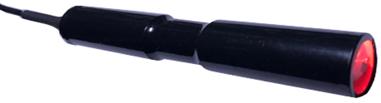
All-in-one and fully waterproof (see video)
See also our NMEA
thermocouple thermometer 0-1000°
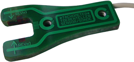
We rebuilt the
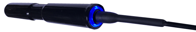
NMEA tachometer in a small plastic tube (epoxy filled), containing
all the parts needed. The south pole of a magnet passing nearby the
front will create the pulses needed to get the speed count (Revolution Per Minute).
The front
red LED will light up every time the
magnet is passing nearby the tube front, so control and installation
will be most easy.
This tachometer probe also has a totalisator counter function. It will
keeping count of the amount of pulses (rotations) since its last power
up.
Application covers propeller axes, engines, machines and other
applications. Most rotation speed or count measurements can simply be
made with this self contained probe...
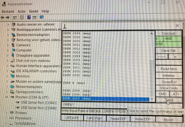
The NMEA string
format and baud rate are user
programmable upto 30 characters including count. This can easily be
done with any comm program (window terminal or else) also via the
output cable or left to the standard output string. For exemple, for
552RPM the standard string will show $RPM552 at 4800B/s.
This 4 leads cable is terminated with an USB-A connector. Use our PC adapter
(see below**) and see the speed
directly on your PC and test
the reaction with the magnet. A small usb to 4
wires adapter is also supplied to connect to your own system.
Power
supply will be fed via the 4 leads output cable with +5 to +16Vdc. Same cable
will also output RS232 TTL
data's at chosen baud rate and
string format. The output
(Tx) and input(Rx) also used to configure or program the probe, is RS232 TTL (0-5Volt!). So never apply more than 5 Volt at
the Tx and Rx wires!
Measuring
5.3x0.85inch
(±140x22mm),
the tacho
is fully
waterproof (IP67) and can also work
immersed! Filled
with epoxy,
these probe is also shock resistant.
Programing
of the output string:
1/
Open window terminal or our communication program exe or zip
and choose current tachometer port and baud rate to make contact with
the probe via an TTL to USB or RS232 adapter.
At this point, actual data received from the tachometer should then be
visible on screen. If not, make sure program baud rate is corresponding
to actual probe baud rate and that the tachometer is powered with 5
volt (see led's).
String
formats are programmed on this model: {NMEA=$ccc#ccc}bT where {NMEA= is the start of the
command, $ccc#ccc the new defined
string terminated with }. c can be replaced
with any readable character and # will be the speed
position in string.
b will be the
new baud rate where 1=1200, 2=2400, 3=4800, 4=9600, 5=19200 and 6=38400 b/s.
T can be 0, 1 or 2. 0 will show no count, 1 show only $CNTxxxxxx and 2
alternate the count with RPM's.
So
as exemples for 1225RPM if we send:
{NMEA=$RPM
#}30
will output
$RPM
1225
at 4800b/s
{NMEA=$turn#}40 will output $turn1225 at 9600b/s
{NMEA=$Tours
# Motor BB}60 will show $Tours
1225 Motor BB
{NMEA=$magRPM
#}20
will output
$magRPM
1225
at 2400b/s
{NMEA=$RPM#(MG)}60 will output $RPM1225(MG) at 38400b/s
{NMEA=$RPM
# (MG)}61 will only output $CNT7542157
{NMEA=$T#}32 output $T1225 $CNT752
$T85
$CNT752
$T85
so we see both speed count and total count each on a new line
alternated. Output line is CR/LF terminated.
{NMEA=Generator
# (50Hertz=3000RPM)}30 Generator
3000 50Hertz=3000RPM
On a
generator shaft, the rotation speed also show the alternator output
frequency. So as we commonly
see, 1500 or 3000 RPM for 50Hertz and 1800
or 3600 RPM for 60Hertz.
{NMEA?
this
command force print last/actual configuration from non volatile memory
EEPROM. It is the config used at powerup. Standard $string is loaded if
error there or at new config...
The
string length should have less than 60 charaters. Any unrecognized
character or character position will cancel the new string
programmation. So the NMEA output string can only be exchanged with a
valid one. The new string takes effect immediately and does not need a
restart. If the baud rate (b)
is changed to a new value, the change will only take effect at next
tachometer powerup so you have time to change it in the pc program too..
The
standard version is to include to your hardware and does not have
rs232 level shifter, so take care not
to apply more than 5 volts to the
Rx and Tx connection when
using positive supply exceeding 5V. However,
positive supply can be +5 to +16V.
The totalisator can count upto over 4 billions pulses and will restart
counting from zero again if overflow. The counter string is
standard $CNTxxxxxx where xxxx show the count. So as seen
before above the counter output is only visible if enabled (T)...
There
is no much to tell about the installation but one should work carefully.
Pls see the differents
small demo movies here...
** When
the probe is not to be included in your NMEA installation and that you
want to read it directly from a computer, you can use one or
these
two wired USB serial adapters PL2303HX or FT232RL that we can
provide...
They are connected at one side (TTL serial) to the probe and the other
side (USB serial) at you computer USB. No need then to connect
any supply adaptor because the probe will take is small power directly
from the USB!
They then give you a extra comm
port that you can read with your PC application or a communication
program like your window Hyper Terminal, our controller program or any other... The
tachometer/counter is then powered via the computer USB with less than
20mA.
Back to panels list
Home
/ start page
mail us /
nous contacter
NMEA
thermocouple exhaust thermometer
Previous
models here below are
obsolete and only shown for reference and service.
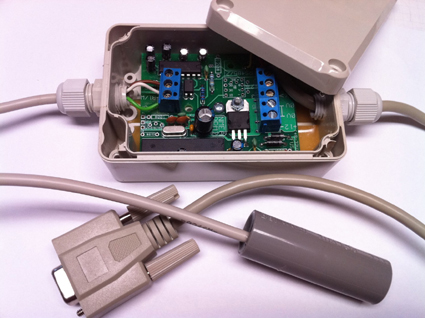
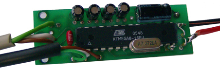
This
tachometer (middel) is a small PCB (58x19x13mm ) to be added to your
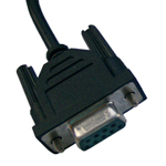
hardware. The optical sensor, DB9
RS232 connector and the supply wire are connected to it. This small PCB
with microcontroller, also have a CMOS/TTL to RS232 level converter
(MAX232) and a supply regulator (78L05).
Output can be directly plugged in the PC RS232 Comm port and any
terminal program will show the velocity rate in RPM.
Application covers propeller axes, engines and other applications
rotation speed measurements.
The power supply requires a clean 7 to 14VDC (negative on black and
positive on red wire). The board battery or a main adapter to 12VDC can
be used. 5VDC can also be used after removing the voltage regulator.
The standard output Format is: $OPRPM*XXXXX at 4800B/s but other output
format were available on demand.
OP = Optical
RPM = Revolution Per Minute (13050RPM
maximum)
*
= Option - , + or nothing. (See Jumper setting)
X = 0-13050 RPM. (no leading zero, (1250RPM =
$OPRPM*1250)
CR and LF close the sentence, sent at half a second
rate. The tachometer does not require
any adjustment and is ready to operate; all wires are already connected.
INFRA RED
TACHOMETER SENSOR (to be connected to the
small
board above) Be very careful when installing probes near a
moving shaft or any moving device. Any moving mechanical
part is dangerous!
The probes wires can be lengthened according to necessity. The
wire thickness is of no particular significance here. Never apply any
electric current to the probes and respect the 3 colored wires
connection order when adding more sensor cable.
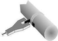 The optical probes are working with a light beam cut at
intervals by the
moving part attached to the rotating shaft. When working adequately,
the sensor red LED will go off each time that the light beam is cuted
by the blind.
The optical probes are working with a light beam cut at
intervals by the
moving part attached to the rotating shaft. When working adequately,
the sensor red LED will go off each time that the light beam is cuted
by the blind.
Mount the probes the way that the infra red light beam is being
cut at each revolution. The moving part occulting the cell on each
revolution needs to have a width of at least 2,5cm (1inch) to ensure a
good reading by high velocity. In fact when far from the center, one
half meter or more, the blend will be about 5cm if the expected RPM
rate is >5000RPM.
Do not expose or install the optical sensor near a strong light source
like fluorescent tube, sunlight and do not place it right next to a
light bulb; it would disturb the receiving cell and the reading.
Install the sensor in the shadow with its connection as high as
possible and keep it dry. Its two red surfaces should remain clean,
even if the sensor is paint in order to prevent disturbing light
breaking inside when not installed in the shadow. Sensor dimension:
45x90x9mm 2xM6 or less bolts.
For safety, use a
piece of rubber for the blind.
We have two interchangable sensors,
optical and magnetic. See at bottom
for the magnetic sensor, working with a small (south pôle)
magnet. See rpmsensor.pdf for more infos
on the sensors.
IP65. In box;
98x65x40mm Mag or Optical sensor.
Output:
LS
= Low Speed (or
whatever wanted)
RPM = Revolution Per Minute
Optional = * - , + or no or any chr wanted.
X = 0 -
13050 RPM. (so 145 RPM = $LSRPM145)
Back to panels list
Home /
start page
mail us /
nous contacter
Please see also our NMEA thermocouple
thermometer